Electrical Engineering (EE) Exam  >  Electrical Engineering (EE) Tests  >  Analog and Digital Electronics  >  Analog Electronics - 1 - Electrical Engineering (EE) MCQ

Analog Electronics - 1 - Electrical Engineering (EE) MCQ


Test Description

10 Questions MCQ Test Analog and Digital Electronics - Analog Electronics - 1

Analog Electronics - 1 for Electrical Engineering (EE) 2024 is part of Analog and Digital Electronics preparation. The Analog Electronics - 1 questions and answers have been prepared according to the Electrical Engineering (EE) exam syllabus.The Analog Electronics - 1 MCQs are made for Electrical Engineering (EE) 2024 Exam. Find important definitions, questions, notes, meanings, examples, exercises, MCQs and online tests for Analog Electronics - 1 below.
Solutions of Analog Electronics - 1 questions in English are available as part of our Analog and Digital Electronics for Electrical Engineering (EE) & Analog Electronics - 1 solutions in Hindi for Analog and Digital Electronics course. Download more important topics, notes, lectures and mock test series for Electrical Engineering (EE) Exam by signing up for free. Attempt Analog Electronics - 1 | 10 questions in 30 minutes | Mock test for Electrical Engineering (EE) preparation | Free important questions MCQ to study Analog and Digital Electronics for Electrical Engineering (EE) Exam | Download free PDF with solutions
Analog Electronics - 1 - Question 1

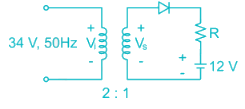
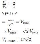
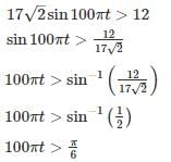
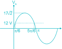
A half-wave rectifier is used to charge a 12V battery through a resistance ‘R’. The input transformer is fed with 34 AC with turns ration 2 : 1. The conduction period of the diode is

Detailed Solution for Analog Electronics - 1 - Question 1


Voltage at secondary winding of the coil is Vs

Voltage across diode

Vp → Vs max

Vn → 12 V

For conduction:

Vp > Vn


Therefore the diode is conducting for the period.

*Answer can only contain numeric values
Analog Electronics - 1 - Question 2

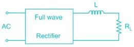
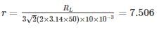
A full-wave rectifier circuit employs inductor filter at its output. If the source frequency is 50 Hz and the inductor value is 10 mH. Find the ripple factor for 100 Ω loads.


Detailed Solution for Analog Electronics - 1 - Question 2

For full wave rectifier using inductor filter at output is

1 Crore+ students have signed up on EduRev. Have you? Download the App
*Answer can only contain numeric values
Analog Electronics - 1 - Question 3

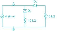
The voltage source VAB = 4 sin ωt is applied to the terminal A and B of the circuit shown In Fig. the diode is assumed to be ideal. The impedance by the circuit across the terminals A and B is ________ kΩ


Detailed Solution for Analog Electronics - 1 - Question 3

When,

D1 → ON; D2 → OFF: RAB = 10 kΩ

D2 → ON; D1 → OFF: RAB = 10 kΩ

∴ The impedance by the circuit across the terminals A and B  of 10 kΩ

Analog Electronics - 1 - Question 4

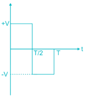
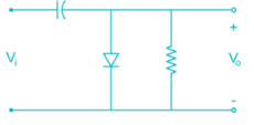
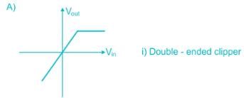
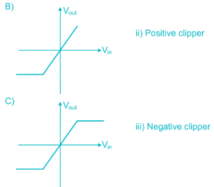
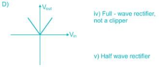
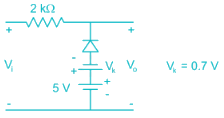
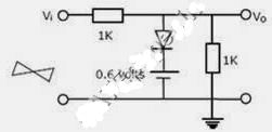
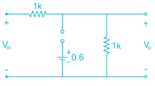
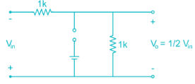
For the damping network shown below, resulting output for the applied Input will be…


Detailed Solution for Analog Electronics - 1 - Question 4

Clamping network “Clamp” a signal to different DC level.

During the Internal O → T/1 → Diode in the ON state during this internal output voltage is directly across the short circuit and Vo = 0 volts


When input switch to -V  state → diode OFF

Applying Kirchhoff’s voltage law around loop we get

-V -V -Vo = 0

Vo = -2V

So output wave form will be,


*Answer can only contain numeric values
Analog Electronics - 1 - Question 5

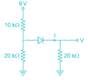
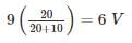
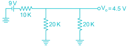
Assuming the diode to be ideal, the current I in the circuit shown is ________ mA.


Detailed Solution for Analog Electronics - 1 - Question 5

The above circuit can be redrawn as:

Assume diode is off:

Voltage across 20 k resistor connected to left of diode is 

This will turn on the diode 

the equivalent circuit is now:

Now the two 20k resistors are in parallel whose equivalent is 10k

this 10 k is in series with other 10k resistor 

9V divides equally among them

V0 = 4.5V 

Cuurent I = 4.5/20 mA

= 0.225 mA

Analog Electronics - 1 - Question 6

The correct option matching List - I to List - II is


Detailed Solution for Analog Electronics - 1 - Question 6

A) In graph ‘A’ the output follows input, but above certain positive input, output stays constant. The circuit is called positive clipper.

B) Similarly the graph ‘B’ is of negative clipper.

C) In this path positive and negative side are clipped, it is a double-ended clipper.

D) In this input output follows relation Vout = |Vin|. This is a full-wave rectifier circuit.

*Answer can only contain numeric values
Analog Electronics - 1 - Question 7

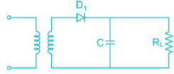
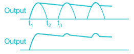
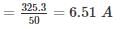
The figure shows a half wave rectifier with a load resistor of 50 Ohms. The input supply voltage is 230V(runs) at 50 Hz. A 10000 μF filter capacitor is added across the load resistor to reduce ripple. The percentage of ripple voltage at the output is ________


Detailed Solution for Analog Electronics - 1 - Question 7

Due to filter capacitor the output voltage is given by waveform


Output DC voltage  Vavg = V= √2 × 230
= 325.3 V


The load current is given by 

This current discharges the capacitor to the load resistance during the interval (t2 to t3)

 The time period of AC voltage. 

= 20 ms (for 50 Hz)

Thus the charge supplied by the capacitor to the load resistance during this interval will be

∆Q = ILT = 6.51 × 20 × 10-3

= 0.1302 coulombs

Peak to peak ripple voltage

Analog Electronics - 1 - Question 8

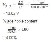
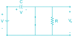
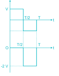
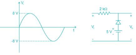
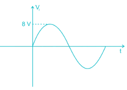
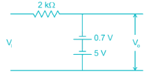
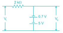
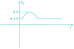
For the diode network shown below is input with voltage pulse Vi. If the knee voltage of the diode is Vk = 0.7 V then the output voltage pulse Vo is
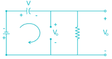
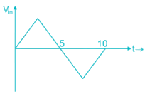
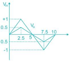
Detailed Solution for Analog Electronics - 1 - Question 8

Given circuit can be written with ideal diode

Is input with


During positive values of Vi < s – Vk i.e. Vi < 4.3 V the diode is in on-state, the diode can be taken as short circuit. The output voltage is simply be voltage across 5V voltage source.


⇒ Vo = s – 0.7 V

= 4.3 V

For Vi > 4.3 V the diode is in off-state the circuit become open circuit hence Vo = Vi
 

The circuit is in on-state for entire negative cycle. Hence Vo = 4.3 V

The wave form of output voltage is
 

*Answer can only contain numeric values
Analog Electronics - 1 - Question 9

In Fig. the Input Vis 100 Hz triangular wave having a peak to peak amplitude of 2 volts and an average value of 0 volts. Given that the diode is ideal, the average value of output Vo is ______


Detailed Solution for Analog Electronics - 1 - Question 9

Time period = 1/f = 1/100 = 10msec


1) During +Ve ½ cycle

Vin = + Ve diode is not forward bias
 

2) During – Ve cycle

Vin = - Ve diode is Reverse Bias


Average value  = 0

*Answer can only contain numeric values
Analog Electronics - 1 - Question 10

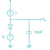
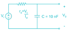
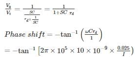
In the circuit shown I is a dC current and Vi is a sinusoidal signal with peak amplitude 10 mV and a frequency 100 kHz. The value of I that will provide a phase shift of -45° at the output is ________. μA (Assume η = 1)


Detailed Solution for Analog Electronics - 1 - Question 10

Opening the current source we get the AC small-signal circuit (η = 1)


I = 157 uA

137 videos|143 docs|71 tests
Information about Analog Electronics - 1 Page
In this test you can find the Exam questions for Analog Electronics - 1 solved & explained in the simplest way possible. Besides giving Questions and answers for Analog Electronics - 1, EduRev gives you an ample number of Online tests for practice

Top Courses for Electrical Engineering (EE)

137 videos|143 docs|71 tests
Download as PDF

Top Courses for Electrical Engineering (EE)