Capacitance MSQ - Free MCQ Test with solutions for Physics
MCQ Practice Test & Solutions: Capacitance MSQ (10 Questions)
You can prepare effectively for Physics Topic wise Tests for IIT JAM Physics with this dedicated MCQ Practice Test (available with solutions) on the important topic of "Capacitance MSQ". These 10 questions have been designed by the experts with the latest curriculum of Physics 2026, to help you master the concept.
Test Highlights:
- - Format: Multiple Choice Questions (MCQ)
- - Duration: 45 minutes
- - Number of Questions: 10
Sign up on EduRev for free to attempt this test and track your preparation progress.

A parallel plate capacitor is charged from a cell and then isolated from it. The separation between the plates is now increased
Detailed Solution: Question 1
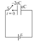
In the figure initial status of capacitance and their connection is shown. Which of the following is correct about this circuit :
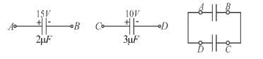
Detailed Solution: Question 2

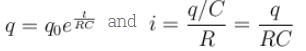
Capacitor C1 of the capacitance 1μF and capacitor C2 of capacitance 2μF are separately charged fully by a common battery. The two capacitors are then separately allowed to discharge through equal resistors at time t = 0.
Detailed Solution: Question 3
Detailed Solution: Question 4
A parallel plate capacitor of capacitance 10µF is connected to a cell of emf 10 Volt and fully charged. Now a dielectric slab (k = 3) of thickness equal to the gap between the plates, is very slowly inserted to completely fill in the gap, keeping the cell connected. During the filling process:
Detailed Solution: Question 5
A parallel plate capacitor is charged and then the battery is disconnected. When the plates of the capacitor are brought closer, then
Detailed Solution: Question 6
The plates of a parallel plate capacitor with no dielectric are connected to a voltage source. Now a dielectric of dielectric constant K is inserted to fill the whole space between the plates with voltage source remaining connected to the capacitor.
Detailed Solution: Question 7
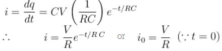
A capacitor (without dielectric) is discharging through a resistor. At some instant a dielectric is inserted between the plates, then which of the following is not true.
Detailed Solution: Question 8
 hence energy decrease
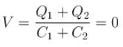
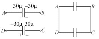
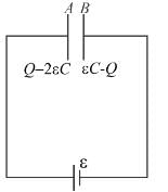
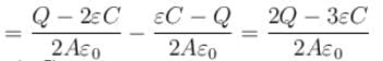
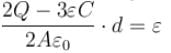
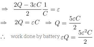
A parallel plate capacitor of capacitance C has charges on its plates initially as shown in the figure. Now at t = 0, the switch S is closed. Select the correct alternative(s) for this circuit diagram.
Detailed Solution: Question 9

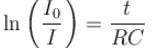
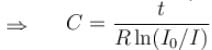
The figure shows, a graph of the current in a discharging circuit of a capacitor through a resistor of resistance 10Ω.
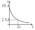
Detailed Solution: Question 10
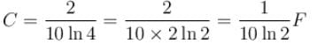

 second.
 Farad., The total heat produced in the circuit will be
  Joules., The thermal power in the resistor will decrease with a time constant
  second.