Chapter Test: Alternating Current - 2 JEE Physics Free MCQs
MCQ Practice Test & Solutions: Chapter Test: Alternating Current - 2 (30 Questions)
You can prepare effectively for JEE Physics for JEE Main & Advanced with this dedicated MCQ Practice Test (available with solutions) on the important topic of "Chapter Test: Alternating Current - 2". These 30 questions have been designed by the experts with the latest curriculum of JEE 2026, to help you master the concept.
Test Highlights:
- - Format: Multiple Choice Questions (MCQ)
- - Duration: 60 minutes
- - Number of Questions: 30
Sign up on EduRev for free to attempt this test and track your preparation progress.

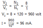
A power transformer (step up) with an 1 : 8 turn ratio has 60 Hz, 120 V across the primary; the load in the secondary is 104 W. The current in the secondary is
Detailed Solution: Question 1
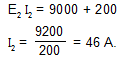
The overall efficiency of a transformer is 90%. The transformer is rated for an output of 9000 watt. The primary voltage is 1000 volt. The ratio of turns in the primary to the secondary coil is 5 : 1. The iron losses at full load are 700 watt. The primary coil has a resistance of 1 ohm.
In the above, the current in the secondary coil is :
Detailed Solution: Question 2

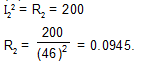
The overall efficiency of a transformer is 90%. The transformer is rated for an output of 9000 watt. The primary voltage is 1000 volt. The ratio of turns in the primary to the secondary coil is 5 : 1. The iron losses at full load are 700 watt. The primary coil has a resistance of 1 ohm.
In the above, the resistance of the secondary coil is approximately :
Detailed Solution: Question 3
In the figure, if IL = 0.8 A, IC = 0.6 A, then I = ?
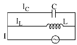
Detailed Solution: Question 5
Detailed Solution: Question 6
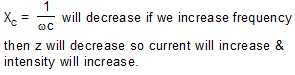
An electric bulb and a capacitor are connected in series with an AC source. On increasing the frequency of the source, the brightness of the bulb :
Detailed Solution: Question 7
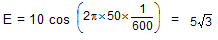
The peak value of an alternating e.m.f given by E = E0 cos w t, is 10 volt and frequency is 50 Hz. At time t = (1/600) sec, the instantaneous value of e.m.f is :
Detailed Solution: Question 9
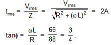
0.21-H inductor and a 88-W resistor are connected in series to a 220-V, 50-Hz AC source. The current in the circuit and the phase angle between the current and the source voltage are respectively.
(Use π = 22/7)
Detailed Solution: Question 10
A resistor R, an inductor L, a capacitor C and voltmeters V1, V2 and V3 are connected to an oscillator in the circuit as shown in the adjoining diagram. When the frequency of the oscillator is increased, upto resonance frequency, the voltmeter reading (at resonance frequency) is zero in the case of :
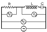
Detailed Solution: Question 11
In a circuit, an inductance of 0.1 Henry and a resistance of 1 Ω are connected in series with an a.c. source of voltage V = 5 sin 10 t. The phase difference between the current and applied voltage will be
Detailed Solution: Question 12
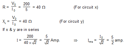
A pure resistive circuit element X when connected to an AC supply of peak voltage 200 V gives a peak current of 5 A which is in phase with the voltage. A second circuit element Y, when connected to the same AC supply also gives the same value of peak current but the current lags behind by 90°. If the series combination of X and Y is connected to the same supply, what will be the rms value of current ?
Detailed Solution: Question 13
Detailed Solution: Question 14
Detailed Solution: Question 15
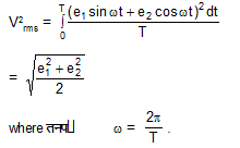
An alternating voltage is given by : e = e1 sin ω t + e2 cos ω t. Then the root mean square value of voltage is given by :
Detailed Solution: Question 16
Detailed Solution: Question 17
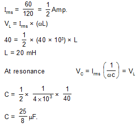
A series LCR circuit containing a resistance of 120 ohm has angular resonance frequency 4 × 10³ rad s–1. At resonance, the voltage across resistance and inductance are 60V and 40 V respectively. The values of L and C are respectively :
Detailed Solution: Question 18
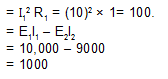
The overall efficiency of a transformer is 90%. The transformer is rated for an output of 9000 watt. The primary voltage is 1000 volt. The ratio of turns in the primary to the secondary coil is 5 : 1. The iron losses at full load are 700 watt. The primary coil has a resistance of 1 ohm.
In the above, the copper loss in the primary coil is :
Detailed Solution: Question 19
Detailed Solution: Question 20
In an LCR circuit, the capacitance is made one-fourth, when in resonance. Then what should be the change in inductance, so that the circuit remains in resonance ?
Detailed Solution: Question 21
Detailed Solution: Question 22
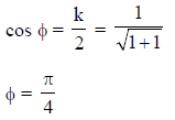
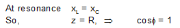
The value of power factor cosf in series LCR circuit at resonance is :
Detailed Solution: Question 23

Detailed Solution: Question 24
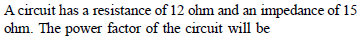
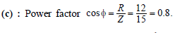
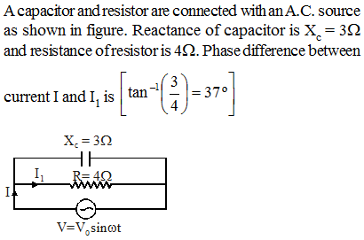
The impedance of a series circuit consists of 3 ohm resistance and 4 ohm reactance. The power factor of the circuit is :
Detailed Solution: Question 25
Detailed Solution: Question 26
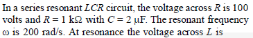
A sinusoidal voltage of peak value 283 V and frequency 50 Hz is applied to a series LCR circuit in which R = 3 Ω, L = 25.48 mH, and C = 796 μF. Power dissipated in the circuit; and the power factor are
Detailed Solution: Question 27
A resistor is connected in series with a capacitor. The voltage across the resistor is vR = (1.20 V) cos(2500 rad/s)t . Capacitive reactance is
Detailed Solution: Question 29
Detailed Solution: Question 30
258 videos|856 docs|206 tests |