Mechanical Engineering Exam  >  Mechanical Engineering Tests  >  SSC JE Mechanical Mock Test Series 2025  >  Fluid Machinery - 2 - Mechanical Engineering MCQ

Fluid Machinery - 2 - Mechanical Engineering MCQ


Test Description

20 Questions MCQ Test SSC JE Mechanical Mock Test Series 2025 - Fluid Machinery - 2

Fluid Machinery - 2 for Mechanical Engineering 2025 is part of SSC JE Mechanical Mock Test Series 2025 preparation. The Fluid Machinery - 2 questions and answers have been prepared according to the Mechanical Engineering exam syllabus.The Fluid Machinery - 2 MCQs are made for Mechanical Engineering 2025 Exam. Find important definitions, questions, notes, meanings, examples, exercises, MCQs and online tests for Fluid Machinery - 2 below.
Solutions of Fluid Machinery - 2 questions in English are available as part of our SSC JE Mechanical Mock Test Series 2025 for Mechanical Engineering & Fluid Machinery - 2 solutions in Hindi for SSC JE Mechanical Mock Test Series 2025 course. Download more important topics, notes, lectures and mock test series for Mechanical Engineering Exam by signing up for free. Attempt Fluid Machinery - 2 | 20 questions in 12 minutes | Mock test for Mechanical Engineering preparation | Free important questions MCQ to study SSC JE Mechanical Mock Test Series 2025 for Mechanical Engineering Exam | Download free PDF with solutions
Fluid Machinery - 2 - Question 1

Two Pelton wheels A and B are having same specific speed and are working under the same head. Wheel A provides 900 kW at 800 RPM. If wheel B produces 100 kW, then its RPM will be

Detailed Solution for Fluid Machinery - 2 - Question 1


For same specific speed and working under the same head i.e. NS1=NS2&H1=H2

N2 = 2400 RPM

Fluid Machinery - 2 - Question 2

Double hemispherical buckets are used in

Detailed Solution for Fluid Machinery - 2 - Question 2

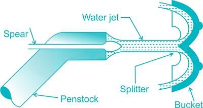
The Pelton wheel or Pelton turbine is a tangential flow impulse turbine. The water strikes the bucket along the tangent of the runner. The shape of the buckets is of double hemispherical cup or bowl. Each bucket is divided into two symmetrical parts by a dividing wall known as splitter. The jet of water strikes on the splitter. The splitter divides the jet into two equal parts and the jet comes out at the outer edge of the bucket. The buckets are shaped in such a way that the jets gets deflected through 160 ° or 170 °. 

Fluid Machinery - 2 - Question 3

Specific speed of a Pelton turbine ranges from

Detailed Solution for Fluid Machinery - 2 - Question 3

Specific speed: It is defined as the speed of a similar turbine working under a head of 1 m to produce a power output of 1 kW. The specific speed is useful to compare the performance of various type of turbines. The specific speed differs for different type of turbines and is same for the model and actual turbine.

1. The specific speed of Pelton wheel turbine (single jet) is in the range of 10-35

2. The specific speed of Pelton wheel turbine (multiple jets) is in the range of 35-60

3. The specific speed of Francis turbine is in the range of 60-300.

4. The specific speed of Kaplan turbine is greater than 300.

Fluid Machinery - 2 - Question 4

Which of the following has got the highest of specific speed?

Detailed Solution for Fluid Machinery - 2 - Question 4

Specific speed: It is defined as the speed of a similar turbine working under a head of 1 m to produce a power output of 1 kW. The specific speed is useful to compare the performance of the various type of turbines. The specific speed differs for the different type of turbines and is the same for the model and actual turbine.

Following are the range of specific speed of different turbines

  • The specific speed of Pelton wheel turbine (single jet) is in the range of 10-35
  • The specific speed of Pelton wheel turbine (multiple jets) is in the range of 35-60
  • The specific speed of Francis turbine is in the range of 60-300.
  • The specific speed of Kaplan/propeller turbine is greater than 300.

So the Kaplan turbine has the highest specific speed.

Fluid Machinery - 2 - Question 5

Cavitation is caused by

Detailed Solution for Fluid Machinery - 2 - Question 5

Cavitation is the formation of gas bubbles of a flowing liquid in a region where the pressure of liquid falls below its vapour pressure i.e. low pressure.

Fluid Machinery - 2 - Question 6

Where is the regulating valve provided in a centrifugal pump

Detailed Solution for Fluid Machinery - 2 - Question 6

The regulating valve is provided on the delivery pipe. It regulates the flow of liquid after its exit from the pump. It is usually a sluice type of valve.

Fluid Machinery - 2 - Question 7

A mono pump is also knows as;

Detailed Solution for Fluid Machinery - 2 - Question 7

Another form of positive acting rotary pump is the single - screw extruder pump typified by the Mono pump. It has a specially shaped metal helical rotor revolves eccentrically within a resilient rubber or plastic double helix, thus creating a continuous forming cavity which processes towards the discharge of the pump. This type of pump is suitable for pumping slurries and pastes, weather Newtonian or Non - Newtonian in character.

Fluid Machinery - 2 - Question 8

Which of the following pump is successfully used for lifting water to the turbine?

Detailed Solution for Fluid Machinery - 2 - Question 8

For lifting water to the turbine, A pump similar to a turbine pipe is used but it works by redirecting water back down to the intake to help lift the water.

While, centrifugal pumps are used to transport fluids by the conversion of rotational kinetic Energy to the hydrodynamic energy of the fluid flow. Reciprocating pumps are not used in turbine function.

Fluid Machinery - 2 - Question 9

Centrifugal pump is based on the principle of_______

Detailed Solution for Fluid Machinery - 2 - Question 9

Centrifugal Pump is a hydraulic machine which converts mechanical energy into hydraulic energy (pressure energy) by the action of centrifugal force acting on the fluid.

Rotation of a centrifugal pump impeller causes the liquid it contains to move outwards from the centre to beyond the circumference of the impeller. The revolving liquid is impelled around the periphery of the impeller by centrifugal effect. Displaced liquid in moving from the casing to the delivery pipe, causes flow in the discharge side of the system.

Fluid Machinery - 2 - Question 10

An impulse hydraulic turbine:

Detailed Solution for Fluid Machinery - 2 - Question 10

Impulse turbine: At the inlet of the turbine, the energy available is only kinetic energy

Example: Pelton Turbine

Reaction Turbine: At the inlet of the turbine, the water possesses kinetic energy as well as pressure energy

Example: Francis Turbine, Kaplan Turbine

Fluid Machinery - 2 - Question 11

Which of the following pumps is used for pumping viscous fluids?

Detailed Solution for Fluid Machinery - 2 - Question 11

A screw pump is a type of positive displacement pump that uses two or more screws that intermesh to pressurize fluids and move them in a system. The screws take in fluid then push it out from the other side while increasing its pressure. In offshore and marine installations, a three-spindle screw pump is often used to pump high-pressure viscous fluids.

Fluid Machinery - 2 - Question 12

For starting an axial flow pump, its delivery valve should be _____.

Detailed Solution for Fluid Machinery - 2 - Question 12

Axial flow pumps have poor suction capability, so require more starting power. They are started against an open valve to minimize the starting power required.

Fluid Machinery - 2 - Question 13

If the discharge of a centrifugal pump is throttled then its suction lift

Detailed Solution for Fluid Machinery - 2 - Question 13

If the discharge of a centrifugal pump is throttled then its suction lift increases. Because of throttling operation, flow rate of centrifugal pump will decrease. As it is assumed that liquid level inside pump is same so hydrostatic pressure is also same. Due to decrease in flow rate, velocity head loss as well as frictional loss decreases, by applying the Bernoulli’s equation, pump static suction pressure will increase.

Fluid Machinery - 2 - Question 14

In centrifugal pumps, maximum efficiency is obtained when the blades are

Detailed Solution for Fluid Machinery - 2 - Question 14

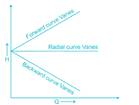
In centrifugal pump backward curve vanes are preferred.

Fluid Machinery - 2 - Question 15

The pressure inside a Pelton turbine casing during working________.

Detailed Solution for Fluid Machinery - 2 - Question 15

Pelton wheel is a kind of impulse turbine. As in case of impulse turbine pressure throughout turbine is constant and equal to atmospheric pressure, so only energy available for turbine is kinetic energy of fluid. There is no change in pressure energy as it takes place in reaction turbine.

Fluid Machinery - 2 - Question 16

By which one of the following, a small quantity of water may be lifted to a great height

Detailed Solution for Fluid Machinery - 2 - Question 16

Hydraulic ram is used to lift small quantity of water to greater height from large quantities of water available at smaller heights.

Fluid Machinery - 2 - Question 17

A single-stage impulse turbine with a diameter of 120 cm runs at 3000 rpm. If the blade speed ratio is 0.42, then, the inlet velocity of steam will be

Detailed Solution for Fluid Machinery - 2 - Question 17

= 188.49 m/s

Blade speed ratio = 0.42

Inlet velocity will be = 188.49/0.42 = 448.78 m/s

Fluid Machinery - 2 - Question 18

A hydraulic coupling

Detailed Solution for Fluid Machinery - 2 - Question 18

The fluid or hydraulic coupling is a device used for transmitting power from driving shaft to the driven shaft, running at different speed, with the help of fluid. There is no mechanical connection between the shafts.

Fluid Machinery - 2 - Question 19

The main function of the draft tube in a hydraulic reaction turbine is to

Detailed Solution for Fluid Machinery - 2 - Question 19

The draft tube is a conduit which connects the runner exit to the tail race where the water is being finally discharged from the turbine. The primary function of the draft tube is to convert kinetic head into pressure head  there by increasing effctive head and efficiency. 

Fluid Machinery - 2 - Question 20

If α is the blade angle at the outlet, then the maximum hydraulic efficiency of an ideal impulse turbine is

Detailed Solution for Fluid Machinery - 2 - Question 20

Hydraulic efficiency of Pelton wheel=  

Here, k = friction factor

u = blade speed/bucket sp eed

v = jet speed

α = blade angle

For maximum efficiency the bucket speed should be halt of jet speed i.e.


Thus, respective maximum efficiency is 

And, if bucket is frictionless, k = 1

3 videos|1 docs|55 tests
Information about Fluid Machinery - 2 Page
In this test you can find the Exam questions for Fluid Machinery - 2 solved & explained in the simplest way possible. Besides giving Questions and answers for Fluid Machinery - 2, EduRev gives you an ample number of Online tests for practice
Download as PDF