Physics: Topic-wise Test- 5 - NEET MCQ
30 Questions MCQ Test - Physics: Topic-wise Test- 5

Two infinitely long conducting parallel rails are connected through a capacitor C as shown in the figure. A conductor of length l is moved with constant speed v0. Which of the following graph truly depicts the variation of current through the conductor with time ?

A student in a lab took a coil and connected it to a 12 V DC source. He measures the steady state current in the circuit to be 4A. He then replaced the 12 V DC source by a 12 V, (w = 50 rad/s) AC source and observes that the reading in the AC ammeter is 2.4 A. He then decides to connect a 2500 mF capacitor in series with the coil and calculate the average power developed in the circuit. Further he also decides to study the variation in current in the circuit (with the capacitor and the battery in series).
Based on the readings taken by the student answer the following questions.
Which of the following graph roughly matches the variations of current in the circuit (with the coil and capacitor connected in the series) when the angular frequency is decreased from 50 rad/s to 25 rad/s ?

The effective value of current i = 2 sin 100p t + 2 sin (100pt + 30º) is
The magnetic field due to current element depends upon which of the following factors:
A circular coil of radius r carries current I. The magnetic field at its center is B. at what distance from the center on the axis of the coil magnetic field will be B/8
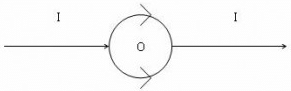
A straight conductor carrying current I is split into circular loop as shown in figure a , the magnetic induction at the center of the circular loop is
No force is exerted by a magnetic field on a stationary –
Along an infinitely long conductor carrying a current of 8 A we keep another conductor of length 5 m carrying a current of 3 A. Both the conductors are 10 cm apart. Find the force on small conductor.
We use _________ to find the direction of force on a current-carrying conductor placed in a magnetic field.
In an iron cored coil the iron core is removed so that the coil becomes an air cored coil. The inductance of the coil will
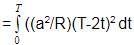
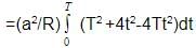
The magnetic flux through a stationary loop with resistance R varies during interval of time T as f = at (T _ t). The heat generated during this time neglecting the inductance of loop will be
The dimensions of permeability of free space can be given by
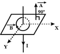
A closed planar wire loop of area A and arbitrary shape is placed in a uniform magnetic field of magnitude B, with its plane perpendicular to magnetic field. The resistance of the wire loop is R. The loop is now turned upside down by 180° so that its plane again becomes perpendicular to the magnetic field. The total charge that must have flowen through the wire ring in the process is
A square coil ABCD is placed in x-y plane with its centre at origin. A long straight wire, passing through origin, carries a current in negative z-direction. Current in this wire increases with time.The induced current in the coil is

Two identical coaxial circular loops carry a current i each circulating in the same direction. If the loops approach each other
In the arrangement shown in given figure current from A to B is increasing in magnitude. Induced current in the loop will


The north pole of a magnet is brought near a coil. The induced current in the coil as seen by an observer on the side of magnet will be
A small conducting rod of length l, moves with a uniform velocity v in a uniform magnetic field B as shown in fig-

The magnetic flux through a surface varies with time as follows:
 = 12t2 + 7t + 3
here, is in milliweber and t is in seconds.
What will be the induced emf at t = 5s?
In Faraday’s experiment if the magnet is moved towards the coil, it results in ____________ in magnetic field B at any point on the wire loop. The _________ shows deflection. Thus emf is induced by changing B.
What is the value of induced e.m.f if a wire is moved between the gap of two poles of a magnetin in 1 s and magnetic flux between the poles is 6 x 10⁻³ Wb?
Two similar circular co-axial loops carry equal current in the same direction. If the loops be brought nearer, the currents in them will
The potential difference V and current i flowing through an a.c. circuit are given by V = 5 cos wt volt, i = 2 sin wt amp. the power dissipated in the circuit.
The rms value of an AC of 50 Hz is 10 amp. The time taken by an alternating current in reaching from zero to maximum value and the peak value will be ;
A voltage of peak value 283 V varying frequency is applied to a series L-C-R combination in which R = 3W; L = 25 mH and C = 400 mF. Then, the frequency (in Hz) of the source at which maximum power is dissipated in the above, is
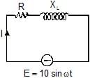
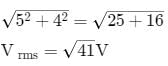
An ac-circuit having supply voltage E consists of a resistor of resistance 3W and an inductor of reactance 4W as shown in the figure. The voltage across the inductor at t = p/w is
An inductive circuit contains a resistance of 10 ohm and an inductance of 2.0 henry. If an ac voltage of 120 volt and frequency of 60 Hz is applied to this circuit, the current in the circuit would be nearly :
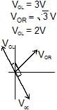
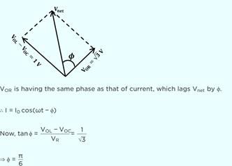
In the circuit shown if the emf of source at an instant is 5V, the potential difference across capacitor at the same instant is 4V. The potential difference across R at that instant may be

The given figure represents the phasor diagram of a series LCR circuit connected to an ac source. At the instant t' when the source voltage is given by V = V0coswt, the current in the circuit will be
Power factor of an L-R series circuit is 0.6 and that of a C_R series circuit is 0.5. If the element (L, C, and R) of the two circuits are joined in series the power factor of this circuit is found to be 1. The ratio of the resistance in the L-R circuit to the resistance in the C-R circuit is


Important Questions for Physics: Topic-wise Test- 5
Physics: Topic-wise Test- 5 MCQs with Answers
Online Tests for Physics: Topic-wise Test- 5
|
© EduRev
|
Education Revolution
|


|


