Electrical Engineering (EE) Exam  >  Electrical Engineering (EE) Tests  >  Basic Electronics Engineering JE (Technical)  >  Test: Analog Electronics Circuits - Electrical Engineering (EE) MCQ

Test: Analog Electronics Circuits - Electrical Engineering (EE) MCQ


Test Description

25 Questions MCQ Test Basic Electronics Engineering JE (Technical) - Test: Analog Electronics Circuits

Test: Analog Electronics Circuits for Electrical Engineering (EE) 2024 is part of Basic Electronics Engineering JE (Technical) preparation. The Test: Analog Electronics Circuits questions and answers have been prepared according to the Electrical Engineering (EE) exam syllabus.The Test: Analog Electronics Circuits MCQs are made for Electrical Engineering (EE) 2024 Exam. Find important definitions, questions, notes, meanings, examples, exercises, MCQs and online tests for Test: Analog Electronics Circuits below.
Solutions of Test: Analog Electronics Circuits questions in English are available as part of our Basic Electronics Engineering JE (Technical) for Electrical Engineering (EE) & Test: Analog Electronics Circuits solutions in Hindi for Basic Electronics Engineering JE (Technical) course. Download more important topics, notes, lectures and mock test series for Electrical Engineering (EE) Exam by signing up for free. Attempt Test: Analog Electronics Circuits | 25 questions in 50 minutes | Mock test for Electrical Engineering (EE) preparation | Free important questions MCQ to study Basic Electronics Engineering JE (Technical) for Electrical Engineering (EE) Exam | Download free PDF with solutions
Test: Analog Electronics Circuits - Question 1

Test: Analog Electronics Circuits - Question 2

1 Crore+ students have signed up on EduRev. Have you? Download the App
Test: Analog Electronics Circuits - Question 3

To prevent a DC return between source and load, it is necessary to use

Test: Analog Electronics Circuits - Question 4

Detailed Solution for Test: Analog Electronics Circuits - Question 4

Correct Answer :- d

Explanation : a) The common emitter amplifier is INVERTING. The inversion is equivalent to 180 degree phase shift. The inversion can be easily seen intuitively without any complex circuit analysis.

b) CB will not provide current gain and input impedance is very low, output impedance is very high therefore it is not used in many applications.

c) The common collector or grounded collector configuration is commonly used where a high impedance input source needs to be connected to a low impedance output load requiring a high current gain.

d) The Darlington transistor is a special type of transistor with a high current gain. It consists of two internally bipolar transistors being connected in cascade.

Test: Analog Electronics Circuits - Question 5

Test: Analog Electronics Circuits - Question 6

Test: Analog Electronics Circuits - Question 7

Test: Analog Electronics Circuits - Question 8

Thermal runaway will take place if the quiescent point is such that

Test: Analog Electronics Circuits - Question 9

The given circuit has a feedback factor of

Test: Analog Electronics Circuits - Question 10

CE configuration is the most preferred transistor configuration when used as a switch because it

Test: Analog Electronics Circuits - Question 11

Consider the following statements regarding a common emitter amplifier. It can be converted into an oscillator by:

1. providing adequate positive feedback

2. phase shifting the output by 180° and feeding this phase-shifted output to the input

3. using only a series tuned circuit as a load on the amplifier

4. using a negative resistance device as a load on the amplifier

Which of the above statements are correct?

Test: Analog Electronics Circuits - Question 12

The PIV rating of the diodes used in power supply circuits are chosen by which one of the following criteria? (Vm is the peak input supply voltage to the rectifier circuit used in the power supply)

Test: Analog Electronics Circuits - Question 13

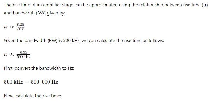
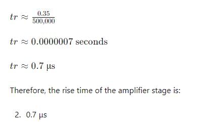
An RC amplifier stage has a bandwidth of 500  kHz. What will be the rise time of this amplifier stage?

Detailed Solution for Test: Analog Electronics Circuits - Question 13


Test: Analog Electronics Circuits - Question 14

Consider the following statements in respect of a transistor R-C coupled amplifier:

1. The low frequency response is determined by the transistor junction capacitors.

2. The high frequency response is limited by coupling capacitors.

3. The Miller capacitance reduces the gain at high frequencies.

4. As the gain is increased the bandwidth gets reduced.

Which of these statements are correct?

Test: Analog Electronics Circuits - Question 15

A CE-amplifier has RL = 10 kΩ. Given hie = 1 kΩ, hfe = 50, hre = 0 and 1/hoe = 40 kΩ. What is the voltage gain?

Test: Analog Electronics Circuits - Question 16

In the given circuit, D1 is an ideal germanium diode and D2 is a silicon diode having its cut-in voltage as 0.7 V, forward resistance as 20Ω and reverse saturation current (ls) as 10 nA. What are the values of I and V for this circuit, respectively?

Test: Analog Electronics Circuits - Question 17

A tuned amplifier has peak output at 2 MHz and quality factor 50. The bandwidth and 3-dB frequencies shall be at what values respectively?

Test: Analog Electronics Circuits - Question 18

Consider the following statements: Tuned amplifiers

1. are wide band amplifiers

2. are used in radio transmitters and receivers

3. performance is determined by Q of the circuit

Which of the statements given above are correct?

Test: Analog Electronics Circuits - Question 19

A feed back amplifier has an open loop gain of - 100. If 4% of the output is fed back in a degenerative loop, what is the closed loop gain of the amplifier?

Test: Analog Electronics Circuits - Question 20

Which one of the following statements is not correct with regard to power amplifiers ?

Test: Analog Electronics Circuits - Question 21

Consider the following statements regarding the class-B power amplifiers (Complementarysymmetry type):

1. The efficiency of the amplifier is higher than that of class-A amplifier

.2. The power output is low.

3. Cross over distortion is present

.4. The standby power dissipation is absent.

Which of the above statements are correct?

Test: Analog Electronics Circuits - Question 22

Consider the following statements :The bias stability of an emitter-bias amplifier circuit improves by

1. decreasing the value of RB.

2. increasing the value of RE.

3. decreasing the value of Re.

4. increasing the value of Rb.

5. Increasing the value of Rc.

Which of the above statements are correct ?

Test: Analog Electronics Circuits - Question 23

Consider the following statements:

When compared with a bridge rectifier, a centre tapped full wave rectifier:

1. Has larger transformer utilization factor.

2. Can be used for floating output terminalsi.e. no input terminal is grounded.

3. Needs two diodes instead of four.

4. Needs diodes of a lower PIV rating.

Which of these statements is/are correct?

Test: Analog Electronics Circuits - Question 24

The output Vdc from the below circuits is

Test: Analog Electronics Circuits - Question 25

A small signal voltage amplifier in common emitter configuration was working satisfactorily.Suddenly its emitter-bypass capacitor (CE) got disconnected. Its:

1. Voltage gain will decrease

2. Voltage gain will increase

3. Bandwidth will decreases

4. Bandwidth will increase

Which of these statements are correct?

25 docs|23 tests
Information about Test: Analog Electronics Circuits Page
In this test you can find the Exam questions for Test: Analog Electronics Circuits solved & explained in the simplest way possible. Besides giving Questions and answers for Test: Analog Electronics Circuits , EduRev gives you an ample number of Online tests for practice

Top Courses for Electrical Engineering (EE)

Download as PDF

Top Courses for Electrical Engineering (EE)