Electrical Engineering (EE) Exam  >  Electrical Engineering (EE) Tests  >  Topicwise Question Bank for Electrical Engineering  >  Test: Basics of Digital Electronics - 1 - Electrical Engineering (EE) MCQ

Test: Basics of Digital Electronics - 1 - Electrical Engineering (EE) MCQ


Test Description

10 Questions MCQ Test Topicwise Question Bank for Electrical Engineering - Test: Basics of Digital Electronics - 1

Test: Basics of Digital Electronics - 1 for Electrical Engineering (EE) 2024 is part of Topicwise Question Bank for Electrical Engineering preparation. The Test: Basics of Digital Electronics - 1 questions and answers have been prepared according to the Electrical Engineering (EE) exam syllabus.The Test: Basics of Digital Electronics - 1 MCQs are made for Electrical Engineering (EE) 2024 Exam. Find important definitions, questions, notes, meanings, examples, exercises, MCQs and online tests for Test: Basics of Digital Electronics - 1 below.
Solutions of Test: Basics of Digital Electronics - 1 questions in English are available as part of our Topicwise Question Bank for Electrical Engineering for Electrical Engineering (EE) & Test: Basics of Digital Electronics - 1 solutions in Hindi for Topicwise Question Bank for Electrical Engineering course. Download more important topics, notes, lectures and mock test series for Electrical Engineering (EE) Exam by signing up for free. Attempt Test: Basics of Digital Electronics - 1 | 10 questions in 30 minutes | Mock test for Electrical Engineering (EE) preparation | Free important questions MCQ to study Topicwise Question Bank for Electrical Engineering for Electrical Engineering (EE) Exam | Download free PDF with solutions
Test: Basics of Digital Electronics - 1 - Question 1

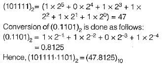
The decimal equivalent of (101111.1101)2 is

Detailed Solution for Test: Basics of Digital Electronics - 1 - Question 1

A binary number can be converted into decimal number by multiplying the binary numbers 1 or 0 by their weight and adding the product. Conversion of 101111 is done as follows: 


Test: Basics of Digital Electronics - 1 - Question 2

Consider the following statements associated with data representation by 1’s and 2‘s complements:
1. The 2’s complement system requires only one arithmetic operation.
2. The 1 ’s complement system requires two arithmetic operations.
3. The 1 's complement is often used in logical manipulations for inversion operation.
4. The 2 ’s complement is used only for arithmetic applications.

Which of the statements given above are correct?

Detailed Solution for Test: Basics of Digital Electronics - 1 - Question 2

1, 3, and 4

Explanation:

1. The 2's complement system requires only one arithmetic operation: This statement is correct. In the 2's complement system, both addition and subtraction can be performed with the same operation (addition). To subtract, we simply add the 2's complement of the number to be subtracted.

2. The 1's complement system requires two arithmetic operations: This statement is incorrect. The 1's complement system also requires only one arithmetic operation (addition) for both addition and subtraction. However, in this system, an end-around carry might be needed for the final result.

3. The 1's complement is often used in logical manipulations for inversion operation: This statement is correct. The 1's complement can be used to invert the bits of a binary number (changing 0s to 1s and vice versa). This operation is useful for logical operations like bitwise NOT.

4. The 2's complement is used only for arithmetic applications: This statement is correct. The 2's complement representation is primarily used for arithmetic operations, such as addition and subtraction, as it simplifies the operations and eliminates the need for separate circuits for these operations.

1 Crore+ students have signed up on EduRev. Have you? Download the App
Test: Basics of Digital Electronics - 1 - Question 3

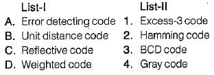
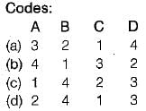
Match List-l with List-ll and select the correct answer using the codes given below the lists:

Detailed Solution for Test: Basics of Digital Electronics - 1 - Question 3
  • “Hamming Code” provides a mathematical way to add one or more parity bits to a data character in order to detect and correct errors.
  • “Gray code” is also called a “unit-distance code” because here two adjacent code numbers differ by only one bit. 
  • “Excess-3 code" is called a “reflective code” because here the code for 9 is the complement of the code for 0, 8 for 1,7 for 2, 6 for 3, and 5 for 4.
  • “BCD code” is as “weighted code” or “8421 code” because it uses the binary number system to specify the decimal number 0 to 9.
Test: Basics of Digital Electronics - 1 - Question 4

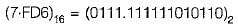
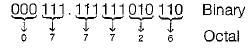
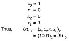
The following two numbers are converted into desired bases x and y respectively.

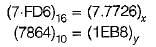
The values of x and y are respectively 

Detailed Solution for Test: Basics of Digital Electronics - 1 - Question 4

The binary number is converted into octal number as follows:

Thus,

(7-FD6)16= (7.7726)8 

On converting the decimal number (7864)10 into hexadecimal number we obtain the result (EB8)16 as follows:

Thus, (7864)10 = (1EB8)16

Test: Basics of Digital Electronics - 1 - Question 5

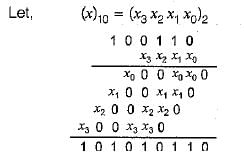
If (100110) x (x)10 = (101010110)2, then the value of x will be equal to 

Detailed Solution for Test: Basics of Digital Electronics - 1 - Question 5

From above multiplication, it is clear that, 

Test: Basics of Digital Electronics - 1 - Question 6

The range of numbers that can be represented using 6-bits in signed binary number representation is

Detailed Solution for Test: Basics of Digital Electronics - 1 - Question 6

In a signed 6-bit binary number representation, the range of numbers is determined by the most significant bit (MSB), which is used as the sign bit.

Here's a breakdown of the range calculation:

  1. Signed 6-bit binary numbers use the first bit (MSB) as the sign bit:

    • 0 indicates a positive number
    • 1 indicates a negative number
  2. Positive numbers (MSB is 0):

    • The remaining 5 bits represent the magnitude.
    • The smallest positive number is 000000 (0 in decimal).
    • The largest positive number is 011111 (31 in decimal).
  3. Negative numbers (MSB is 1):

    • The 2's complement method is used to represent negative numbers.
    • The smallest negative number is 100000 (-32 in decimal).
    • The largest negative number is 111111 (-1 in decimal).

Thus, the range of numbers that can be represented using 6-bit signed binary number representation is from -32 to 31.

Test: Basics of Digital Electronics - 1 - Question 7

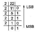
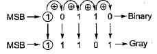
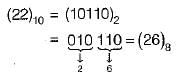
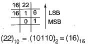
A decimal number (22)10 may be represented by the following ways: 

Detailed Solution for Test: Basics of Digital Electronics - 1 - Question 7

The binary equivalent of (22)10 = (10110)2 as follows:

∴  (22)10 = (10110)2

  • The GRAY code of (10110)2 is obtained as follows:

Thus, (10110)2 = (11101)gray

  • The octal equivalent of (22)10 = (26)8 obtained as follows:

  • The hexadecimal equivalent of (22)10 obtained as follows:

Test: Basics of Digital Electronics - 1 - Question 8

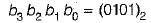
The 7-bit even parity Hamming code of the binary bits 0101 is

Detailed Solution for Test: Basics of Digital Electronics - 1 - Question 8

Given,

∴ The required 7-bit even parity Hamming code is ( 0 1 0 0 1 0 1).

Test: Basics of Digital Electronics - 1 - Question 9

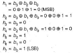
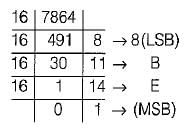
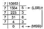
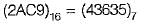
If (2AC9)16 = (Z)7, then the value of Z is

Detailed Solution for Test: Basics of Digital Electronics - 1 - Question 9

Thus, (2AC9)16 - (10,953)10

Now, the decimal number is converted into the number of base 7 as follows:

Thus

Test: Basics of Digital Electronics - 1 - Question 10

Assertion (A): Digital circuits are often called switching circuits.
Reason (R): Each type of digital circuit obeys a certain set of logic rules.

Detailed Solution for Test: Basics of Digital Electronics - 1 - Question 10

Digital circuits are often called switching circuits, because the voltages in a digital circuit are assumed to be switching from one value to another instantaneously, that is, the transition time is assumed to be zero.
Reason is also a correct statement because digital circuit is a logic circuit, because each type of digital circuit obeys a certain set of logic rules. Hence, both assertion and reason are true but reason is not the correct explanation of assertion.

212 tests
Information about Test: Basics of Digital Electronics - 1 Page
In this test you can find the Exam questions for Test: Basics of Digital Electronics - 1 solved & explained in the simplest way possible. Besides giving Questions and answers for Test: Basics of Digital Electronics - 1, EduRev gives you an ample number of Online tests for practice

Top Courses for Electrical Engineering (EE)

Download as PDF

Top Courses for Electrical Engineering (EE)