Electrical Engineering (EE) Exam  >  Electrical Engineering (EE) Tests  >  Engineering Services Examination (ESE) Mock Test Series 2024  >  Test: ESE Electrical - 10 - Electrical Engineering (EE) MCQ

Test: ESE Electrical - 10 - Electrical Engineering (EE) MCQ


Test Description

30 Questions MCQ Test Engineering Services Examination (ESE) Mock Test Series 2024 - Test: ESE Electrical - 10

Test: ESE Electrical - 10 for Electrical Engineering (EE) 2024 is part of Engineering Services Examination (ESE) Mock Test Series 2024 preparation. The Test: ESE Electrical - 10 questions and answers have been prepared according to the Electrical Engineering (EE) exam syllabus.The Test: ESE Electrical - 10 MCQs are made for Electrical Engineering (EE) 2024 Exam. Find important definitions, questions, notes, meanings, examples, exercises, MCQs and online tests for Test: ESE Electrical - 10 below.
Solutions of Test: ESE Electrical - 10 questions in English are available as part of our Engineering Services Examination (ESE) Mock Test Series 2024 for Electrical Engineering (EE) & Test: ESE Electrical - 10 solutions in Hindi for Engineering Services Examination (ESE) Mock Test Series 2024 course. Download more important topics, notes, lectures and mock test series for Electrical Engineering (EE) Exam by signing up for free. Attempt Test: ESE Electrical - 10 | 150 questions in 180 minutes | Mock test for Electrical Engineering (EE) preparation | Free important questions MCQ to study Engineering Services Examination (ESE) Mock Test Series 2024 for Electrical Engineering (EE) Exam | Download free PDF with solutions
Test: ESE Electrical - 10 - Question 1

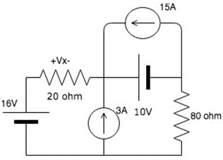
Find the voltage due to the 15A source.

basic-electrical-engineering-questions-answers-superposition-theorem-q5

Detailed Solution for Test: ESE Electrical - 10 - Question 1

Due to the 15V source, the 10V and 16V sources get shorted and the 3A source acts as an open circuit. Since the 10V source is shorted, it acts as a low resistance path and current flows only within that loop and do not flow to the 20 ohm resistor. Hence the voltage is 0V.

Test: ESE Electrical - 10 - Question 2

Superposition theorem does not work for________

Detailed Solution for Test: ESE Electrical - 10 - Question 2

Power across an element is not equal to the power across it due to all the other sources in the system. The power in an element is the product of the total voltage and the total current in that element.

1 Crore+ students have signed up on EduRev. Have you? Download the App
Test: ESE Electrical - 10 - Question 3

In superposition theorem, when we consider the effect of one current source, all the other current sources are____________

Detailed Solution for Test: ESE Electrical - 10 - Question 3

In the superposition theorem, when we consider the effect of one current source, all the other current sources are opened. The superposition theorem states that in a linear circuit with multiple sources, the total response is the sum of the individual responses caused by each source acting independently.

To apply the superposition theorem, we analyze the circuit under consideration one source at a time while deactivating or "turning off" the other sources. For current sources, this means opening the circuit or disconnecting the current source being examined from the rest of the circuit.

By opening the circuit of all other current sources, we can isolate the effect of a single current source and calculate its contribution to the overall circuit response.

Therefore, the correct answer is B: Opened.

Test: ESE Electrical - 10 - Question 4

In A parallel circuit, with any number of impedances, The voltage across each impedance is?

Detailed Solution for Test: ESE Electrical - 10 - Question 4

In a parallel circuit, each impedance (or resistor) is connected across the same voltage source. This means that the voltage across each impedance in a parallel circuit is the same.

When multiple impedances are connected in parallel, they share the same voltage across their terminals. This is because all components in a parallel configuration have the same voltage applied to them.

This characteristic of parallel circuits is often used in applications where different loads or devices require the same voltage supply. By connecting them in parallel, each device receives the same voltage, ensuring consistent operation.

Therefore, the correct answer is A: The same for all impedances.

Test: ESE Electrical - 10 - Question 5

In a parallel circuit, we consider _____________ instead of impedance.

Detailed Solution for Test: ESE Electrical - 10 - Question 5

In a parallel circuit, when analyzing the behavior of components, we consider admittance instead of impedance. Admittance is the reciprocal of impedance and represents the ease with which alternating current (AC) can flow through a component.

While impedance (Z) is a complex quantity that combines resistance (R) and reactance (X) (which can be inductive or capacitive), admittance (Y) is also a complex quantity that combines conductance (G) and susceptance (B) (which can be inductive or capacitive). The relationship between impedance and admittance is given by the formulas:

Y = 1/Z
Z = 1/Y

In a parallel circuit, the total admittance of the circuit is the sum of the individual admittances of the components connected in parallel. By considering admittance, we can analyze the behavior of components in terms of their conductance and susceptance, which helps in calculating currents and understanding the flow of AC through the parallel circuit.

Therefore, the correct answer is D: Admittance.

Test: ESE Electrical - 10 - Question 6

As the impedance increases, the admittance ____________

Detailed Solution for Test: ESE Electrical - 10 - Question 6

Impedance and admittance are reciprocal quantities. Impedance (Z) represents the opposition to the flow of alternating current (AC) in a circuit, while admittance (Y) represents the ease with which AC can flow through a circuit.

The relationship between impedance and admittance is given by the formulas:

Y = 1/Z
Z = 1/Y

As impedance increases, the value of Z becomes larger, indicating greater opposition to the flow of current. Conversely, as admittance increases, the value of Y becomes larger, indicating easier flow of current.

Since impedance and admittance are reciprocals, when impedance increases, admittance decreases, and vice versa. This means that as the impedance of a circuit increases, the admittance decreases, representing a greater resistance to the flow of AC.

Therefore, the correct answer is B: Decreases.

Test: ESE Electrical - 10 - Question 7

A relay coil is connected to a 210 V, 50 Hz supply. If it has resistance of 30Ω and an inductance of 0.5 H, the apparent power is

Detailed Solution for Test: ESE Electrical - 10 - Question 7


Apparent power 

Test: ESE Electrical - 10 - Question 8

For a 2-port symmetrical bilateral network, iftransmission parameters A = 3 and B = 1Ω , the value ofparameter C is

Detailed Solution for Test: ESE Electrical - 10 - Question 8

In a 2-port symmetrical bilateral network, the transmission parameters (also known as ABCD parameters) are commonly used to describe the network's behavior. The transmission parameters consist of four variables: A, B, C, and D.

The parameter C represents the transfer conductance, which indicates the conductance between the output port and the input port of the network.

Given that A = 3 and B = 1Ω, we can use the formula to calculate the value of C:

C = (A * B - 1) / B

C = (3 * 1 - 1) / 1

C = (3 - 1) / 1

C = 2 / 1

C = 2 S (Siemens)

Therefore, the value of parameter C is 2 S, or in the answer options, 8 S (B).

Test: ESE Electrical - 10 - Question 9

The voltage between ______________ is called line voltage.

Detailed Solution for Test: ESE Electrical - 10 - Question 9

The voltage between line and line is called line voltage. And the voltage between line and neutral point is called phase voltage. The currents flowing through the phases are called the phase currents, while those flowing in the lines are called the line currents.

Test: ESE Electrical - 10 - Question 10

The three impedances Z1 = 20∠30⁰Ω, Z2 = 40∠60⁰Ω, Z3 = 10∠-90⁰Ω are delta-connected to a 400V, 3 – Ø system. Determine the phase current IR.

Detailed Solution for Test: ESE Electrical - 10 - Question 10

Taking VRY = V∠0⁰ as a reference phasor, and assuming RYB phase sequence, we have VRY = 400∠0⁰V Z1 = 20∠30⁰Ω = (17.32 + j10)Ω IR = (400∠0o)/(20∠30o) = (17.32 - j10) A.

Test: ESE Electrical - 10 - Question 11

Which of the following statements is true?

Detailed Solution for Test: ESE Electrical - 10 - Question 11

In electromagnetism, when considering the relationship between electric and magnetic fields, the cross product is used to describe the interaction between vectors. The cross product of two vectors, such as v (velocity) and B (magnetic field), gives rise to a third vector called E (electric field).

Mathematically, the relationship between the vectors can be expressed as:

E = v × B

This equation states that the electric field E is the cross product of the velocity vector v and the magnetic field vector B.

Therefore, the correct answer is A: E is the cross product of v and B.

Test: ESE Electrical - 10 - Question 12

Find the force due to a current element of length 2cm and flux density of 12 tesla. The current through the element will be 5A.

Detailed Solution for Test: ESE Electrical - 10 - Question 12

The force due to a current element is given by F = BI x L. Thus F = 12 x 5 x 0.02 = 1.2 units.

Test: ESE Electrical - 10 - Question 13

Let x1(t) and x2(t) be periodic signals with fundamental periods T1 and T2 respectively. Which of the following must be a rational number for x(t)=x1(t)+x2(t) to be periodic? 

Detailed Solution for Test: ESE Electrical - 10 - Question 13

Let T be the period of the signal x(t)
⇒ x(t + T) = x1(t + mT1) + x2(t + nT2)
Thus, we must have
mT= nT= T
⇒ (T1/T2) = (k/m) = a rational number.

Test: ESE Electrical - 10 - Question 14

Which of the following is true?

Detailed Solution for Test: ESE Electrical - 10 - Question 14

If XN represents the N point DFT of the sequence xN in the matrix form, then we know that

Test: ESE Electrical - 10 - Question 15

If X(z) has M finite zeros and N finite poles, then which of the following condition is true?

Detailed Solution for Test: ESE Electrical - 10 - Question 15

If X(z) has M finite zeros and N finite poles, then X(z) can be rewritten as X(z) = z - M + N.X'(z).
So, if N > M then z has a positive power. So, it has |N - M| zeros at origin.

Test: ESE Electrical - 10 - Question 16

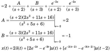
Determine the time signal x(t) corresponding to given X (s) and choose correct option.
Q. 

Detailed Solution for Test: ESE Electrical - 10 - Question 16


Test: ESE Electrical - 10 - Question 17

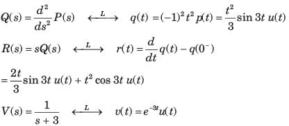
Determine the time signal x(t) corresponding to given X (s) and choose correct option.
Q. 

Detailed Solution for Test: ESE Electrical - 10 - Question 17


Test: ESE Electrical - 10 - Question 18

Determine the Fourier series coefficient for given periodic signal x(t).
Q. x(t) = sin2t

Detailed Solution for Test: ESE Electrical - 10 - Question 18


The fundamental period of sin2( t) is π and 

Test: ESE Electrical - 10 - Question 19

The Fourier series of an odd periodic function, contains only
Select one:

Detailed Solution for Test: ESE Electrical - 10 - Question 19

If periodic function is odd the dc term a0 = 0 and also cosine terms (even symmetry)
It contains only sine terms.
The correct answer is: sine terms

Test: ESE Electrical - 10 - Question 20

Consider a discrete-time periodic signal

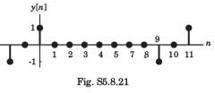
with period N = 10. Also y[n] = x[n] - x[n - 1]
Q. The fundamental period of y[n] is

Detailed Solution for Test: ESE Electrical - 10 - Question 20

y[n] is shown is fig. S5.8.21. It has fundamental

period of 10.

Test: ESE Electrical - 10 - Question 21

To reduce side lobes, in which region of the filter the frequency specifications has to be optimized?

Detailed Solution for Test: ESE Electrical - 10 - Question 21

In filter design, the transition band refers to the frequency range between the stop band and the pass band. It is the region where the filter response transitions from attenuating frequencies in the stop band to allowing frequencies in the pass band.

To reduce side lobes in a filter, it is crucial to optimize the frequency specifications in the transition band. Side lobes are undesired ripples or fluctuations in the filter response that occur outside the main pass band. By carefully designing and optimizing the frequency specifications within the transition band, it is possible to minimize the amplitude of these side lobes.

The stop band refers to the range of frequencies that the filter is designed to attenuate or reject. The pass band, on the other hand, is the range of frequencies that the filter allows to pass through without significant attenuation.

Therefore, to reduce side lobes, the frequency specifications need to be optimized in the transition band (option C)

Test: ESE Electrical - 10 - Question 22

For a decimation-in-time FFT algorithm, which of the following is true?

Detailed Solution for Test: ESE Electrical - 10 - Question 22

In a decimation-in-time Fast Fourier Transform (FFT) algorithm, the input sequence is typically shuffled or rearranged before performing the FFT computation. This rearrangement is done to ensure efficient computation and to exploit the symmetry properties of the FFT algorithm.

The input sequence is typically shuffled using a bit-reversal permutation. This permutation swaps the positions of the elements in the input sequence according to their binary representations in reverse order. The shuffling is done to group the input samples in a way that simplifies the computation of the FFT.

After the FFT computation, the output sequence is typically in the order of increasing frequency components, also known as "in order". This means that the output sequence will be arranged from low frequencies to high frequencies.

Therefore, in a decimation-in-time FFT algorithm, the input is shuffled (option C) using a bit-reversal permutation, and the output is in order (not shuffled) based on frequency components.

Test: ESE Electrical - 10 - Question 23

 Which of the following equation is true? 

Detailed Solution for Test: ESE Electrical - 10 - Question 23

We know that:

Test: ESE Electrical - 10 - Question 24

What is the expression for cutoff frequency in terms of pass band gain?

Detailed Solution for Test: ESE Electrical - 10 - Question 24

We know that:

Test: ESE Electrical - 10 - Question 25

The DC gain of the system represented by the following transfer function is

Detailed Solution for Test: ESE Electrical - 10 - Question 25

Given transfer function is

Converting above transfer function in time-constant form, we get:

Hence, dc gain is

Test: ESE Electrical - 10 - Question 26

The signal flow graph shown below has M number of forward path and N number of individual loops.

Q. ​What are the values of M and N ?

Detailed Solution for Test: ESE Electrical - 10 - Question 26

There are three forward paths. The gain of the forward path are:

  • M1 = G1G2G3G4G5
  • M2 = G1G6G4G5
  • M3 = G1G2G7

There are four loops with loop gains:
N1= - G4H1

N2= - G2G7H2

N3= - G6G4G5H2

N4= - G2G3G4G5H2

Test: ESE Electrical - 10 - Question 27

Assertion (A): With the increase in bandwidth of the system the response of the system becomes fast.
Reason (R): Damping ratio of the system decreases with the increase in bandwidth.

Detailed Solution for Test: ESE Electrical - 10 - Question 27

When BW is increased, the system response becomes fast due to fait in rise time (tr).
With the increase in bandwidth of the system, damping ratio (ξ) decreases.
Thus, both assertion and reason are true but, reason is not the correct explanation of assertion.

Test: ESE Electrical - 10 - Question 28

The characteristic equation of a linear discrete-data control system is given as:
F(z) = z3 + z2 + z + K = 0,
Where K is a real constant.
What is the range of values of K so that the system is stable?

Detailed Solution for Test: ESE Electrical - 10 - Question 28

Given, F(z) = z3 + z2 + z + k = 0
Using bilinear transformation, we put z = in the above characteristic equation.

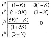
or, (1 - K)r3 + (1 + 3K) r2 + 3(1 - K)r + 3 + K = 0 
Routh’s array is:

For the system to be stable, we have:
1 - K > 0 or K < 1    ...(i)

3 + K > 0 or K > - 3    ..(iii)
From equation (i), (ii) and (iii) the range of values of K for stability is, 0 < K < 1.

Test: ESE Electrical - 10 - Question 29

For the loop transfer function:

the angle of departure at s = j for K > 0 is

Detailed Solution for Test: ESE Electrical - 10 - Question 29


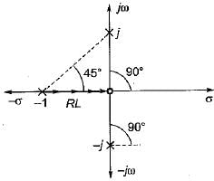
Here, P = 3, Z = 1, P - Z = 2
No. of branches of RL terminating at zero = 1.
No. of branches of RL termination at infinity = 2

Here, two branches of RL has to terminate at infinity.
Thus, the two imaginary poles will terminate at infinity.
Hence, we need to find angle of departure for which we join all poles and zeros with the imaainarv Dole at s = j1.

Thus, φ = (90° -135°) = - 45°
∴  Angle of departure is,
φD = 180° + φ
= 180° - 45° = 135°

Test: ESE Electrical - 10 - Question 30

The magnitude plot of the open loop transfer function G(s) of a certain system is shown in figure below.
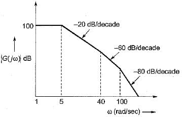
If the system is of minimum phase type, then the open-loop transfer function G(s) will be given by:

Detailed Solution for Test: ESE Electrical - 10 - Question 30

Since, the system is of minimum phase type, it has no poles or zeros in the right hand side of s-plane.
⇒ There will be three corner frequencies at: ω1 = 5 rad/s
∴ T1 = 1/ω1 = 0.2 sec
(one pole added at ω1 = 5 rad/s)
ω2 = 40 rad/s
∴ T2 = 1/ω2 = 0.025 sec
(two pole added at ω1 = 40 rad/s)
and ω3 = 100 rad/s
∴ T3 = 1/ω3 = 0.01 sec
(two poles added at ω3 = 100 rad/s)
So, open loop T.F. is

Now, 20 log K = 100
∴ K = 105
Thus, 

View more questions
12 tests
Information about Test: ESE Electrical - 10 Page
In this test you can find the Exam questions for Test: ESE Electrical - 10 solved & explained in the simplest way possible. Besides giving Questions and answers for Test: ESE Electrical - 10, EduRev gives you an ample number of Online tests for practice

Top Courses for Electrical Engineering (EE)

Download as PDF

Top Courses for Electrical Engineering (EE)