Test: Electronics - 1 - Physics MCQ
20 Questions MCQ Test GATE Physics Mock Test Series 2025 - Test: Electronics - 1

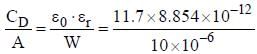
A Silicon PN junction diode under reverse bias lias depletion region of widlit 10 μm. The relative peunittivity of Silicon. εr =11.7 and the permittivity of free space ε0 = 8.85 x 10⁻¹² F/m . The depletion capacitance of the diode per square meter is


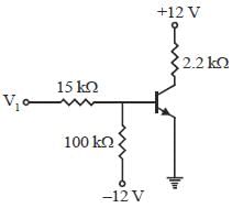
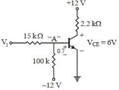
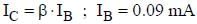
For the transistor shown below. β = 30 and VCEQ = 6 V. The value ofV1 is


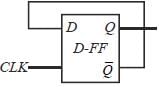
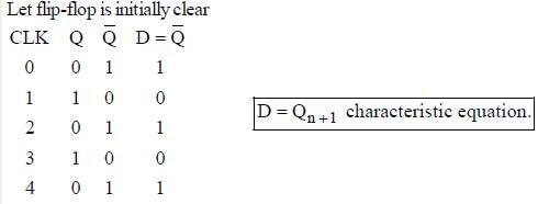

The truth table for an S-R flip-flop has how many VALID entries?
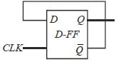
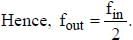
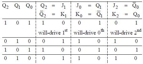
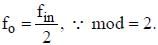
The three-stage Johnson counter as shown in figure below is clocked at a constant frequency of fc from the starting state of Q2Q1Q0 =101. The frequecny of output Q2Q1Q0 will be

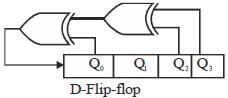
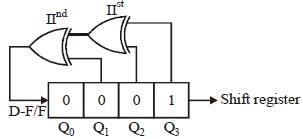
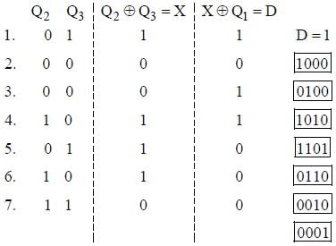
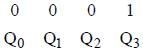
A 4-bit light shift register is initialized to value 1000 for (Q3, Q2, Q1, Q0 ). The D input is derived from Q0, Q2 and Q3 through two XOR gates as shown in figure. The pattern 1000 will appear at
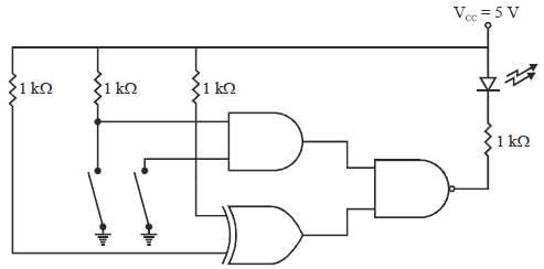
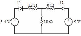
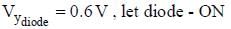
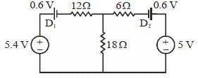
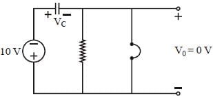
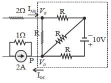
In the circuit shown beolw diodes has cutin voltage of 0.6 V. The dioide in ON state are
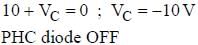
 ...(a)
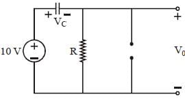
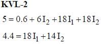 .....(b)
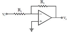

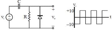
For the circuit shown below the input voltage vi is as shown in figure.
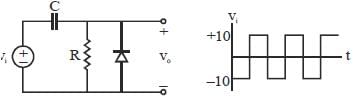
Assume the RC time constant large and cutin voltage of diode Vγ = 0. The output voltage vo is


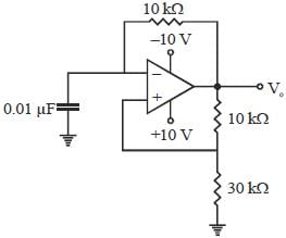
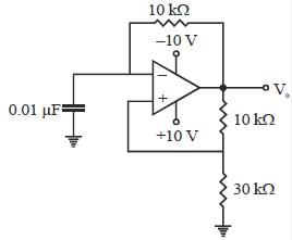
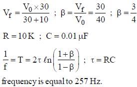
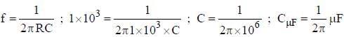
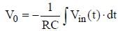
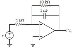
The value of C required for sinusoidal oscillation of frequency 1 kHz in the following circuit is

Consider an op-amp circuit shown in figure, input to the circuit is shown in figure, Initially voltage across capacitor is zero,
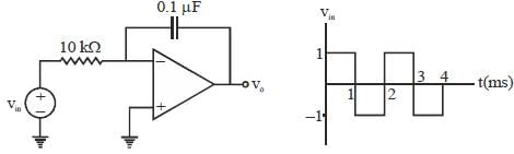
the output waveform will be
 is finite
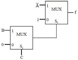
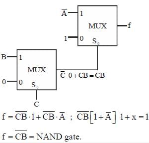
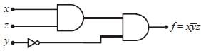
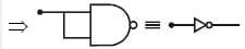
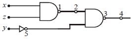
Minimum number of two input NAND gate to design function f =  ...........

The full scale output of a 10-bit DAC is 5 V. The resolution is_____________mV

|
1 docs|34 tests
|


Important Questions for Electronics - 1
Electronics - 1 MCQs with Answers
Online Tests for Electronics - 1 GATE Physics Mock Test Series 2025
|
© EduRev
|
Education Revolution
|


|


