GATE Electrical Engineering (EE) Test: First Order RL & RC Circuits - 1
MCQ Practice Test & Solutions: Test: First Order RL & RC Circuits - 1 (10 Questions)
You can prepare effectively for Electrical Engineering (EE) GATE Electrical Engineering (EE) Mock Test Series 2027 with this dedicated MCQ Practice Test (available with solutions) on the important topic of "Test: First Order RL & RC Circuits - 1". These 10 questions have been designed by the experts with the latest curriculum of Electrical Engineering (EE) 2026, to help you master the concept.
Test Highlights:
- - Format: Multiple Choice Questions (MCQ)
- - Duration: 30 minutes
- - Number of Questions: 10
Sign up on EduRev for free to attempt this test and track your preparation progress.

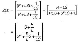
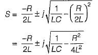
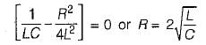
The poles of the impedance Z(s) for the network shown in figure below will be real and coincident if
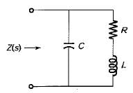
Detailed Solution: Question 1
In the complex frequency S= σ + jω, ω has the unit of radian/sec and σ has the unit of

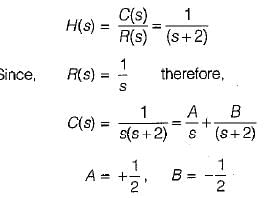
A system is described by the transfer function 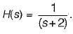 The value of its step response at a very large time will be close to
The value of its step response at a very large time will be close to Detailed Solution: Question 3
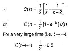
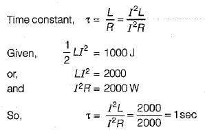
At a certain current, the energy stored in iron cored coil is 1000 J and its copper loss is 2000 W. The time constant (in second) of the coil is
Detailed Solution: Question 4
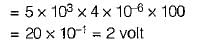
A ramp voltage vi(t) = 100t V is applied to a differentiator circuit with R = 5 kΩ and C=4μF.The maximum output voltage is
Detailed Solution: Question 5

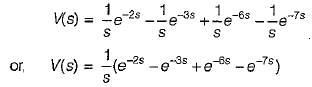
The Laplace transform of the waveform below is
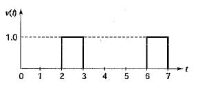
Detailed Solution: Question 6
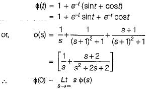
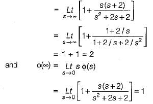
The initial and final values of 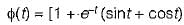 are given by
are given by Detailed Solution: Question 7
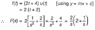
The Laplace transform of the ramp function shown below is
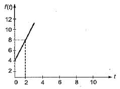
Detailed Solution: Question 8
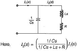
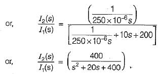
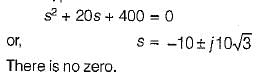
The poles and zeros of the transfer function  for the circuit shown below are located at
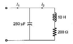
for the circuit shown below are located atDetailed Solution: Question 9
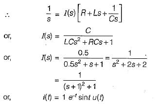
A capacitor of 0.5 F is initially charged to 1 volt and is subjected to discharge at t = 0 across a LR series circuit where 1 = 1 H; R = 2 Ω. The current i(t) for t> 0 is
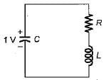
Detailed Solution: Question 10

26 docs|247 tests |