Electrical Engineering (EE) Exam  >  Electrical Engineering (EE) Tests  >  Topicwise Question Bank for Electrical Engineering  >  Test: Frequency Response & Resonance- 2 - Electrical Engineering (EE) MCQ

Test: Frequency Response & Resonance- 2 - Electrical Engineering (EE) MCQ


Test Description

15 Questions MCQ Test Topicwise Question Bank for Electrical Engineering - Test: Frequency Response & Resonance- 2

Test: Frequency Response & Resonance- 2 for Electrical Engineering (EE) 2024 is part of Topicwise Question Bank for Electrical Engineering preparation. The Test: Frequency Response & Resonance- 2 questions and answers have been prepared according to the Electrical Engineering (EE) exam syllabus.The Test: Frequency Response & Resonance- 2 MCQs are made for Electrical Engineering (EE) 2024 Exam. Find important definitions, questions, notes, meanings, examples, exercises, MCQs and online tests for Test: Frequency Response & Resonance- 2 below.
Solutions of Test: Frequency Response & Resonance- 2 questions in English are available as part of our Topicwise Question Bank for Electrical Engineering for Electrical Engineering (EE) & Test: Frequency Response & Resonance- 2 solutions in Hindi for Topicwise Question Bank for Electrical Engineering course. Download more important topics, notes, lectures and mock test series for Electrical Engineering (EE) Exam by signing up for free. Attempt Test: Frequency Response & Resonance- 2 | 15 questions in 45 minutes | Mock test for Electrical Engineering (EE) preparation | Free important questions MCQ to study Topicwise Question Bank for Electrical Engineering for Electrical Engineering (EE) Exam | Download free PDF with solutions
Test: Frequency Response & Resonance- 2 - Question 1

A series RLC circuit consist of resistance of 10 ohms, an inductance of 0.1 H and a capacitance of 0.001 μF. The frequency at resonance is

Detailed Solution for Test: Frequency Response & Resonance- 2 - Question 1


Test: Frequency Response & Resonance- 2 - Question 2

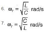
Which of the following Is not true for a series RLC resonant circuit?

Detailed Solution for Test: Frequency Response & Resonance- 2 - Question 2


When Δω increases, selectivity decreases and vice-versa.
Also, Vc|max occurs at,

1 Crore+ students have signed up on EduRev. Have you? Download the App
Test: Frequency Response & Resonance- 2 - Question 3

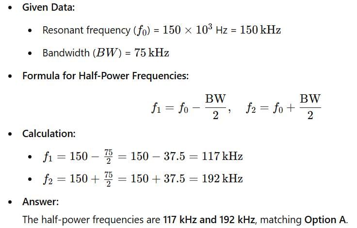
The half-power frequencies of a series resonant circuit where the resonant frequency is 150 x 103 Hz and the bandwidth is 75 kHz will be respectively given by

Detailed Solution for Test: Frequency Response & Resonance- 2 - Question 3

Given, Δf = 75 kHz = f2 - f1...(i)

On solving equations (i) and (ii), we get
f= 117 kHz and f2 = 192 kHz 

Test: Frequency Response & Resonance- 2 - Question 4

For the tank circuit shown below, the circulating current at resonance is given by

Detailed Solution for Test: Frequency Response & Resonance- 2 - Question 4

At resonance, XL = XC
∴ IL = IC (for parallel resonant circuit)
Hence, 

or, 

or, 

(IL=IC = circulating current)

Test: Frequency Response & Resonance- 2 - Question 5

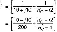
The value of RC in the circuit shown below to yield resonance will be
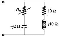
Detailed Solution for Test: Frequency Response & Resonance- 2 - Question 5

Here,
 
At resonance,
Img [Y] = 0
or, 

Test: Frequency Response & Resonance- 2 - Question 6

A resonating circuit has 10ft resistance, if the supply is 10 Ω, the power at half power frequency will be

Detailed Solution for Test: Frequency Response & Resonance- 2 - Question 6

At resonance,

Now, power at half power frequency

Test: Frequency Response & Resonance- 2 - Question 7

For the circuit shown below, what are the values of R1, and R2 so that the circuit will resonate at all frequencies?
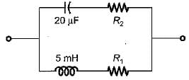
Detailed Solution for Test: Frequency Response & Resonance- 2 - Question 7

For the given circuit to resonate at all frequency,


Note: Resonant frequency of given circuit is

Thus, 

Test: Frequency Response & Resonance- 2 - Question 8

The value of current I1 in the circuit shown below is
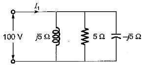
Detailed Solution for Test: Frequency Response & Resonance- 2 - Question 8

Since XL = XL, therefore given circuit will be at resonance
∴ I= 100/5 = 20 A

Test: Frequency Response & Resonance- 2 - Question 9

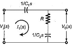
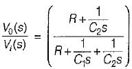
The transfer function  of the network shown below is

Detailed Solution for Test: Frequency Response & Resonance- 2 - Question 9

The given circuit in s-domain is shown below.

Now, 

and 

So, 


or, 

Test: Frequency Response & Resonance- 2 - Question 10

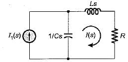
The poles and zeros of the transfer function  for the circuit shown below are located at
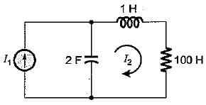
Detailed Solution for Test: Frequency Response & Resonance- 2 - Question 10


or, 

or, 


Thus, there is no-zero for T.F.  


Poles are at:
2s2 + 200s + 1 = 0
or, 

or, 

= -100 ±99.99
= 0 or -200
Hence, poles are at: s = 0, -200

Test: Frequency Response & Resonance- 2 - Question 11

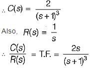
The output of a linear system for a unit step input is given by t2 e-t. The transfer function is given by

Detailed Solution for Test: Frequency Response & Resonance- 2 - Question 11

Given, C(t) = t2e-t

Test: Frequency Response & Resonance- 2 - Question 12

A constant voltage but variable frequency ac source feeds L and C in parallel as shown below:
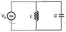
The impedance seen by source is Z
1. Z is zero when f = 0.
2. Z is zero when f = infinity.
3. Z is infinite when f = 0.
4. Z is infinite when f = infinity.
5. resonant frequency, 

From above, the correct answer is

Detailed Solution for Test: Frequency Response & Resonance- 2 - Question 12

Resonant frequency,

Also, 


When f = 0, ω = 0 and z = 0.
When f = ∞, co = ∞ and z= 0.

Test: Frequency Response & Resonance- 2 - Question 13

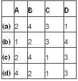
Match List- I (Types of filters) with List- II (Attenuation band) and select the correct answer using the codes given below the lists:
List -I
A. Low pass
B. High pass
C. Band pass
D. Band stop

List-II
1. 0 → f2, f1 → ∞
2. fc → ∞
3. f1 → f2
4. 0 → fc

Codes:
Test: Frequency Response & Resonance- 2 - Question 14

The transfer function is for an active

Detailed Solution for Test: Frequency Response & Resonance- 2 - Question 14

When s → 0 , H (0) → 0
When s → ∞, H(∞) → 0
Hence, given T.F. is for a band pass filter.

Test: Frequency Response & Resonance- 2 - Question 15

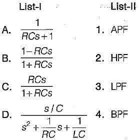
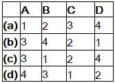
Match List- I (Transfer function) with List- II (Type of filter) and select the correct answer using the codes given below the lists:
Codes:
Detailed Solution for Test: Frequency Response & Resonance- 2 - Question 15

Putting s → 0 and s → ∞ we can find the type of the filter.

212 tests
Information about Test: Frequency Response & Resonance- 2 Page
In this test you can find the Exam questions for Test: Frequency Response & Resonance- 2 solved & explained in the simplest way possible. Besides giving Questions and answers for Test: Frequency Response & Resonance- 2, EduRev gives you an ample number of Online tests for practice

Top Courses for Electrical Engineering (EE)

Download as PDF

Top Courses for Electrical Engineering (EE)