Electrical Engineering (EE) Exam  >  Electrical Engineering (EE) Test  >  Network Theory (Electric Circuits)  >  Test: Millman's Theorem - Electrical Engineering (EE) MCQ

Millman's Theorem - Free MCQ Practice Test with solutions, GATE EE Network


MCQ Practice Test & Solutions: Test: Millman's Theorem (9 Questions)

You can prepare effectively for Electrical Engineering (EE) Network Theory (Electric Circuits) with this dedicated MCQ Practice Test (available with solutions) on the important topic of "Test: Millman's Theorem". These 9 questions have been designed by the experts with the latest curriculum of Electrical Engineering (EE) 2026, to help you master the concept.

Test Highlights:

  • - Format: Multiple Choice Questions (MCQ)
  • - Duration: 45 minutes
  • - Number of Questions: 9

Sign up on EduRev for free to attempt this test and track your preparation progress.

Test: Millman's Theorem - Question 1

Find the current flowing through the resistor R4?

Detailed Solution: Question 1
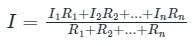

Applying KCL at node A.

32 V – 240 + 20 V – 200 + 5 V = 0
57 V = 440
V = 440/57
= 0.96 A

Test: Millman's Theorem - Question 2

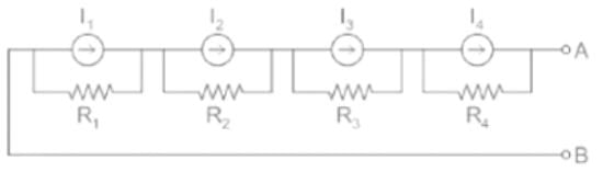
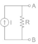
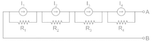
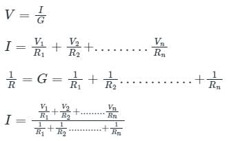
According to Millman’s Theorem, if there are n current sources with n internal resistances respectively, in series, then these sources are replaced by?

Detailed Solution: Question 2

Millman’s Theorem:
(1) voltage source: It is states that – when a number of voltage sources (V1, V2, V3……… Vn) are in parallel having internal resistance (R1, R2, R3………….Rn) respectively, the arrangement can replace by a single equivalent voltage source V in series with an equivalent series resistance R. 


The equivalent circuit parameter

(2) Current source: It is state that – when a number of current sources (I1, I2, I3......In) are in series having internal resistance (R1, R2, R3………….Rn) respectively, the arrangement can replace by a single equivalent current source I in parallel with an equivalent series resistance R.


The equivalent circuit parameter

R = R1 + R2 + R3 ...... Rn

Test: Millman's Theorem - Question 3

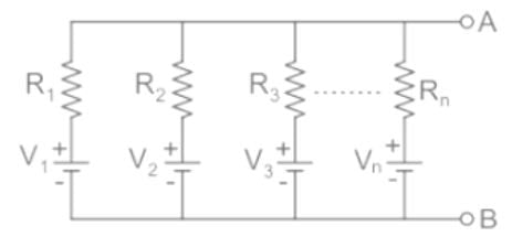
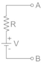
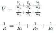
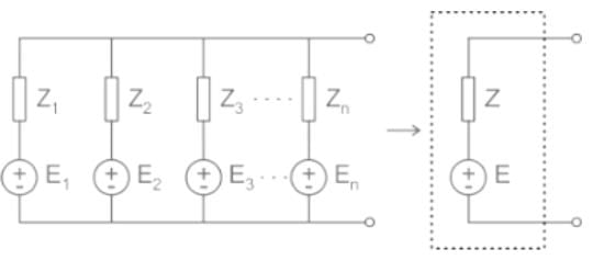
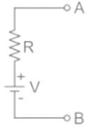
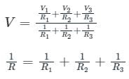
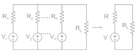
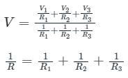
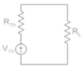
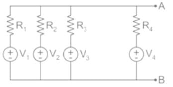
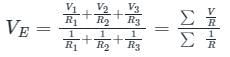
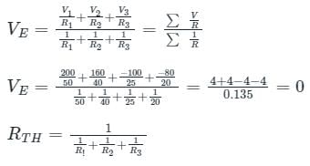
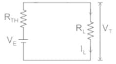
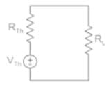
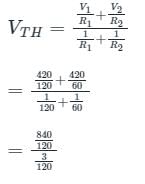
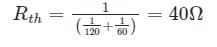
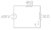
Name the theorem which states that if several ideal voltage sources in series are connected with impedance in parallel, then the circuit may be replaced with a single ideal source in series with an impedance (represented in the figure below).

Detailed Solution: Question 3

Millman’s theorem:

  • It is a very useful theorem to find out the voltage across the load and the current through the load.
  • It is also called as parallel generator theorem.
  • It is helpful to reduce a mixture of voltage and current sources connected in parallel to a single equivalent voltage or current source.

1. voltage source

It is stated that – when a number of voltage sources (V1, V2, V3……… Vn) are in parallel having internal resistance (R1, R2, R3………….Rn) respectively, the arrangement can replace by a single equivalent voltage source V in series with an equivalent series resistance R. 

The equivalent circuit parameter

2. Current source:

It is state that – when a number of current sources (I1, I2, I3......In) are in series having internal resistance (R1, R2, R3………….Rn) respectively, the arrangement can replace by a single equivalent current source I in parallel with an equivalent series resistance R.


The equivalent circuit parameter
I = I1 + I2 + I3 ....... In
R = R1 + R2 + R3 ...... Rn

Test: Millman's Theorem - Question 4

What does Millman’s theorem yield?

Detailed Solution: Question 4

Milliman's Theorem:

Millman's Theorem states that it is possible to replace numbers of voltage sources with finite internal resistance operating in parallel with a single voltage source with a series of equivalent resistance.

According to Ohm's Law:

V = IR

Test: Millman's Theorem - Question 5

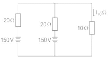
In the circuit shown below, the current through 10Ω resistor is:

Detailed Solution: Question 5

Concept:
Millman’s Theorem:
It is stated that – when a number of voltage sources (V1, V2, V3……… Vn) are in parallel having internal resistance (R1, R2, R3………….Rn) respectively, the arrangement can replace by a single equivalent voltage source V in series with an equivalent series resistance R.


The equivalent circuit parameter

V = equivalent voltage
R = equivalent resistance
Calculation:
From Millman's theorem, the above circuit can be redrawn as

Where

Test: Millman's Theorem - Question 6

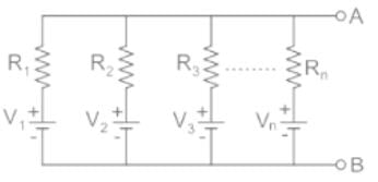
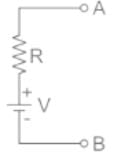
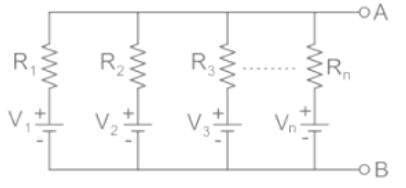
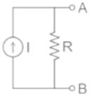
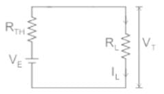
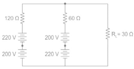
Which of the following helps in finding a single equivalent voltage source of the circuit shown in the figure?

Detailed Solution: Question 6

Millman’s Theorem:
(1) voltage source: It is states that – when a number of voltage sources (V1, V2, V3……… Vn) are in parallel having internal resistance (R1, R2, R3………….Rn) respectively, the arrangement can replace by a single equivalent voltage source V in series with an equivalent series resistance R. 


The equivalent circuit parameter

(2) Current source: It is state that – when a number of current sources (I1, I2, I3......In) are in series having internal resistance (R1, R2, R3………….Rn) respectively, the arrangement can replace by a single equivalent current source I in parallel with an equivalent series resistance R.


The equivalent circuit parameter

R = R+ R2 + R3 ...... Rn

Test: Millman's Theorem - Question 7

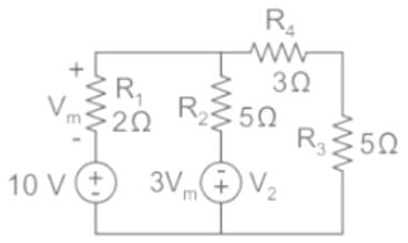
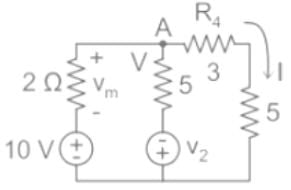
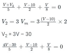
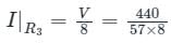
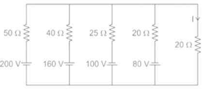
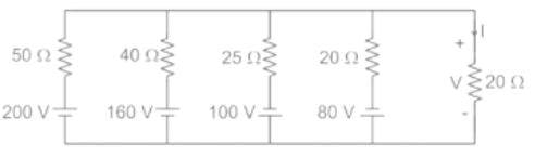
The current I flowing in the circuit shown below in amperes is ________.

Detailed Solution: Question 7

Concept:
Let us have a circuit as shown in the below figure a

Here V1, V2, and V3 are voltages of respectively 1st, 2nd, and 3rd branch, and R1, R2, and R3 are their respective resistances.

IL, RL, and VT are load current, load resistance, and terminal voltage respectively.

Now, this complex circuit can be reduced easily to a single equivalent voltage source with a series resistance with the help of Millman’s Theorem as shown in figure b.

The value of equivalent voltage VE is specified as per Millman’s theorem will be

This VE is nothing but Thevenin’s voltage and Thevenin’s resistance RTH can be determined by shorting the voltage source.
So RTH will be obtained as


Now load current and terminal voltage can be easily found by

Calculation:
Given circuit diagram


RTH = 1/0.135 = 7.40 Ω 

RL = 20 Ω 
Load current I will be as follows

Therefore the current I flowing in the circuit shown below in amperes is 0 A

Test: Millman's Theorem - Question 8

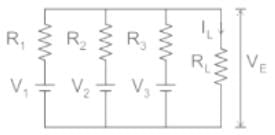
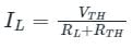
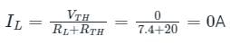
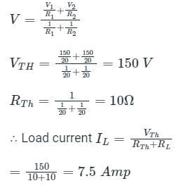
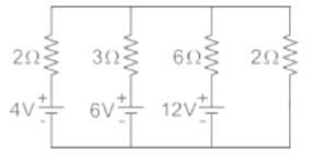
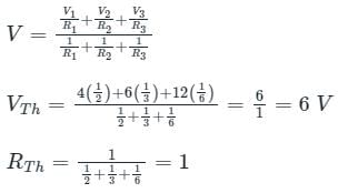
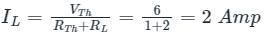
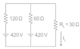
Using Millman’s theorem, find the current through the load resistance, RL of 2 Ω resistance shown below:

Detailed Solution: Question 8

It is states that – when a number of voltage sources (V1, V2, V3……… Vn) are in parallel having internal resistance (R1, R2, R3………….Rn) respectively, the arrangement can replace by a single equivalent voltage source V in series with an equivalent series resistance R. 


The equivalent circuit parameter

V = equivalent voltage
R = equivalent resistance
Calculation:
From Millman's theorem, the above circuit can be redrawn as

where

∴ Load current 

Test: Millman's Theorem - Question 9


In the circuit shown above, the current through RL is

Detailed Solution: Question 9


Applying Millman's theorem we get

= 420 V


IL = 420/70
= 6 A

74 videos|151 docs|62 tests
Information about Test: Millman's Theorem Page
In this test you can find the Exam questions for Test: Millman's Theorem solved & explained in the simplest way possible. Besides giving Questions and answers for Test: Millman's Theorem, EduRev gives you an ample number of Online tests for practice
Download as PDF