Electrical Engineering (EE) Exam  >  Electrical Engineering (EE) Tests  >  Power Electronics  >  Test: Power Electronics - 1 - Electrical Engineering (EE) MCQ

Test: Power Electronics - 1 - Electrical Engineering (EE) MCQ


Test Description

25 Questions MCQ Test Power Electronics - Test: Power Electronics - 1

Test: Power Electronics - 1 for Electrical Engineering (EE) 2024 is part of Power Electronics preparation. The Test: Power Electronics - 1 questions and answers have been prepared according to the Electrical Engineering (EE) exam syllabus.The Test: Power Electronics - 1 MCQs are made for Electrical Engineering (EE) 2024 Exam. Find important definitions, questions, notes, meanings, examples, exercises, MCQs and online tests for Test: Power Electronics - 1 below.
Solutions of Test: Power Electronics - 1 questions in English are available as part of our Power Electronics for Electrical Engineering (EE) & Test: Power Electronics - 1 solutions in Hindi for Power Electronics course. Download more important topics, notes, lectures and mock test series for Electrical Engineering (EE) Exam by signing up for free. Attempt Test: Power Electronics - 1 | 25 questions in 25 minutes | Mock test for Electrical Engineering (EE) preparation | Free important questions MCQ to study Power Electronics for Electrical Engineering (EE) Exam | Download free PDF with solutions
Test: Power Electronics - 1 - Question 1

A cycloconverter can be

Detailed Solution for Test: Power Electronics - 1 - Question 1

The output frequency can be more or less than input frequency.

Test: Power Electronics - 1 - Question 2

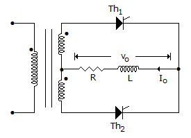
In the below figure the average load current is 15 A. The rms value of transformer secondary current is
Detailed Solution for Test: Power Electronics - 1 - Question 2

RMS secondary current = = 15/1.414 = 10.608 A.

1 Crore+ students have signed up on EduRev. Have you? Download the App
Test: Power Electronics - 1 - Question 3

In a 3 phase fully controlled converter the firing frequency is

Detailed Solution for Test: Power Electronics - 1 - Question 3

It is a 6 pulse converter.

Test: Power Electronics - 1 - Question 4

Two thyristor of same rating and same specifications

Detailed Solution for Test: Power Electronics - 1 - Question 4

Turn on and turn off times of similar SCRs may not be same.

Test: Power Electronics - 1 - Question 5

The amount of dielectric heating is inversely proportional to frequency.

Detailed Solution for Test: Power Electronics - 1 - Question 5

It is proportional to frequency.

Test: Power Electronics - 1 - Question 6

A semiconverter feeding an RLE load operates in

Detailed Solution for Test: Power Electronics - 1 - Question 6

Semiconvertor operates only in first quadrant.

Test: Power Electronics - 1 - Question 7

The phenomenon of overlap in converter operation due to

Detailed Solution for Test: Power Electronics - 1 - Question 7

Source inductance delays turn off and hence causes overlap.

Test: Power Electronics - 1 - Question 8

A thyristor has a maximum allowable junction temperature of 120ºC and the ambient temperature is 40ºC. If thermal resistance is 1.6º C/W, the maximum allowable internal power dissipation is

Detailed Solution for Test: Power Electronics - 1 - Question 8

.

Test: Power Electronics - 1 - Question 9

For a 12 pulse operation, the two 6 pulse units are fed by

Detailed Solution for Test: Power Electronics - 1 - Question 9

30� phase difference is necessary.

Test: Power Electronics - 1 - Question 10

In a single phase full wave converter (M - 2 connection) feeding a highly inductive load, the firing angle for each thyristor is a in the respective half cycle. The period of conduction of each thyristor is

Detailed Solution for Test: Power Electronics - 1 - Question 10

Since conduction is from a to p + a, period of conduction is p in each half cycle.

Test: Power Electronics - 1 - Question 11

An SCR is triggered at 40ºin the positive half cycle only. The average anode current is 50 A. If the firing angle is changed to 80º, the average anode current is likely to be

Detailed Solution for Test: Power Electronics - 1 - Question 11

.

Test: Power Electronics - 1 - Question 12

The characteristics of a non-linear resistance is i = kv4. If i becomes 100 times, v becomes

Detailed Solution for Test: Power Electronics - 1 - Question 12

v ∝ (i)1/4 ∝ (100)1/4 ≈ 3.

Test: Power Electronics - 1 - Question 13

In a step down chopper using pulse width modulation, Ton = 3 x 10⁻³ and Toff = 1 x 10⁻³ s. The chopping frequency is

Detailed Solution for Test: Power Electronics - 1 - Question 13

.

Test: Power Electronics - 1 - Question 14

Thyristors are suitable for dc circuit breakers but not for ac circuit breakers.

Detailed Solution for Test: Power Electronics - 1 - Question 14

They are suitable for both dc and ac circuit breakers.

Test: Power Electronics - 1 - Question 15

Assertion (A): Inverters and choppers use fast switching thyristors

Reason (R): Fast switching SCR has low turn off time.

Detailed Solution for Test: Power Electronics - 1 - Question 15

Low turn off time enables fast switching.

Test: Power Electronics - 1 - Question 16

The value of capacitor C for dynamic equalising circuit of series connected thyristors is determined by

Detailed Solution for Test: Power Electronics - 1 - Question 16

Value of C is proportional to maximum difference between reverse charge of SCRs in series.

Test: Power Electronics - 1 - Question 17

A chopper

Detailed Solution for Test: Power Electronics - 1 - Question 17

A chopper is a dc-ac converter. It converts a fixed dc voltage into a variable dc voltage.

Test: Power Electronics - 1 - Question 18

Assertion (A): If the duty cycle of chopper is low the current would not become discontinuous

Reason (R): If the time constant L/R of the load in chopper is low the current may become discontinuous.

Detailed Solution for Test: Power Electronics - 1 - Question 18

If duty cycle is low, current may become discontinuous.

Test: Power Electronics - 1 - Question 19

An electric heater is controlled by thyristors through on-off control. If a = 0.4, the heating is

Detailed Solution for Test: Power Electronics - 1 - Question 19

Vl = V a. Therefore Vl2 - V2 (a). Heating is proportional to a.

Test: Power Electronics - 1 - Question 20

A two winding transformer is feeding a single phase half wave rectifier circuit. The load is purely resistive. The rms value of transformer secondary current is Is and rms value of load current in Irms. Then

Detailed Solution for Test: Power Electronics - 1 - Question 20

.

Test: Power Electronics - 1 - Question 21

The terminals of a power BJT are called

Detailed Solution for Test: Power Electronics - 1 - Question 21

In a BJT terminals are emitter, base and collector irrespective of rating.

Test: Power Electronics - 1 - Question 22

In single phase half wave regulator, the average current over one full cycle

Detailed Solution for Test: Power Electronics - 1 - Question 22

The input current during positive half cycle is less than that during negative half cycle.

Test: Power Electronics - 1 - Question 23

The dynamic equalising circuit consists of a series combination of capacitor C and resistor RC across each thyristor. This resistance RC (along with parallel connected diode)

Detailed Solution for Test: Power Electronics - 1 - Question 23

Discharge current flows through Re .

Test: Power Electronics - 1 - Question 24

A single phase semiconverter is feeding a highly inductive load and has freewheeling diode across the load. The waveshapes of output voltage and output current

Detailed Solution for Test: Power Electronics - 1 - Question 24

When freewheeling diode conducts output current exists but output voltage is zero.

Test: Power Electronics - 1 - Question 25

A full-wave rectifier uses 2 diodes. The internal resistance of each diode is 20 Ω. The transformer RMS secondary voltage from centre tap to each end of the secondary is 50 V and the load resistance is 980 Ω. Mean load current will be

Detailed Solution for Test: Power Electronics - 1 - Question 25

Concept:

Center tapped full wave rectifier:

  • The Center tapped full-wave rectifier is a device used to convert the AC input voltage into DC voltage at the output terminals.
  • It employs a transformer with the secondary winding tapped at the center point. And it uses only two diodes, which are connected to the opposite ends of a center-tapped transformer as shown in the figure below.
  • The center tap is usually considered as the ground point or the zero voltage reference point.

Analysis:

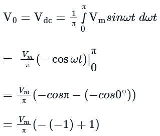
The DC output voltage or average output voltage can be calculated as follows,


V0 = 2Vm / π 

Now we can calculate the average or mean current of load by dividing the average load voltage by load resistance RL. Therefore mean load current is given by

I0 = V0 / RL

If the internal resistance of the diode is given in that case mean load current I0 = V0 / (RL + r)

Where r = internal resistance of the diode.

Calculation:

Given that 

Rms value of supply voltage V = 50 V

The internal resistance of diode r = 20 Ω 

The load resistance RL = 980 Ω 

Maximum voltage on the secondary side Vm = √2 V = √2 × 50 = 70.7 V
Average or DC output voltage V0 = 
Average or mean load current is

5 videos|50 docs|46 tests
Information about Test: Power Electronics - 1 Page
In this test you can find the Exam questions for Test: Power Electronics - 1 solved & explained in the simplest way possible. Besides giving Questions and answers for Test: Power Electronics - 1 , EduRev gives you an ample number of Online tests for practice

Top Courses for Electrical Engineering (EE)

5 videos|50 docs|46 tests
Download as PDF

Top Courses for Electrical Engineering (EE)