Mechanical Engineering Exam  >  Mechanical Engineering Tests  >  Strength of Materials (SOM)  >  Test: SFD & BMD Level - 3 - Mechanical Engineering MCQ

Test: SFD & BMD Level - 3 - Mechanical Engineering MCQ


Test Description

20 Questions MCQ Test Strength of Materials (SOM) - Test: SFD & BMD Level - 3

Test: SFD & BMD Level - 3 for Mechanical Engineering 2024 is part of Strength of Materials (SOM) preparation. The Test: SFD & BMD Level - 3 questions and answers have been prepared according to the Mechanical Engineering exam syllabus.The Test: SFD & BMD Level - 3 MCQs are made for Mechanical Engineering 2024 Exam. Find important definitions, questions, notes, meanings, examples, exercises, MCQs and online tests for Test: SFD & BMD Level - 3 below.
Solutions of Test: SFD & BMD Level - 3 questions in English are available as part of our Strength of Materials (SOM) for Mechanical Engineering & Test: SFD & BMD Level - 3 solutions in Hindi for Strength of Materials (SOM) course. Download more important topics, notes, lectures and mock test series for Mechanical Engineering Exam by signing up for free. Attempt Test: SFD & BMD Level - 3 | 20 questions in 60 minutes | Mock test for Mechanical Engineering preparation | Free important questions MCQ to study Strength of Materials (SOM) for Mechanical Engineering Exam | Download free PDF with solutions
Test: SFD & BMD Level - 3 - Question 1

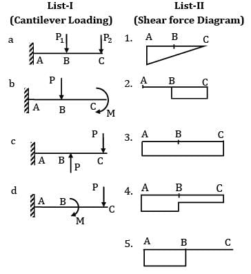
Loading and shear force diagrams are given

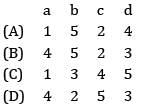
Codes:


Detailed Solution for Test: SFD & BMD Level - 3 - Question 1

Test: SFD & BMD Level - 3 - Question 2

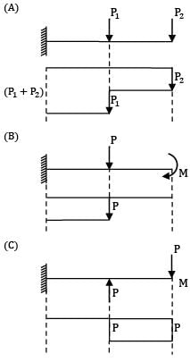
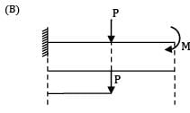
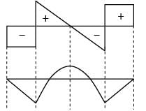
The shear force diagram is shown above for a loaded beam. The corresponding bending moment diagram is represented by
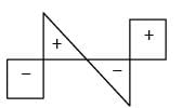
Detailed Solution for Test: SFD & BMD Level - 3 - Question 2

When SF = Constant BM should have a linear variation.

When SF linearly varying BM should vary parabolically.

Both the conditions are satisfied for option (A).

1 Crore+ students have signed up on EduRev. Have you? Download the App
Test: SFD & BMD Level - 3 - Question 3

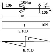
Consider the following statements for a simply supported beam subjected to a couple of 10 kN-m at its mid-span.

1. Bending moment is zero at the ends and maximum at the center

2. Bending moment is constant over the entire length of the beam

3. Shear force is constant over the entire length of the beam

4. Shear force is zero over the entire length of the beam Which of the statements given above are correct?

Detailed Solution for Test: SFD & BMD Level - 3 - Question 3

Test: SFD & BMD Level - 3 - Question 4

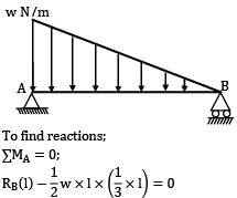
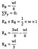
A simply supported beam of span ‘l’ subjected to a load linearly varying from zero at one end to w/m at the other, develops a maximum shear force of

Detailed Solution for Test: SFD & BMD Level - 3 - Question 4

The maximum shear force will occur at A.

Test: SFD & BMD Level - 3 - Question 5

The left half of a simply supported beam of span “L” is loaded with u. d. l of w/meter run. The point of maximum B.M will occur at

Detailed Solution for Test: SFD & BMD Level - 3 - Question 5

We know RA + RB = wL / 2

Taking moments about A

For maximum B.M, S. F must be change sign shear force at

x = RA − wx = 0

Test: SFD & BMD Level - 3 - Question 6

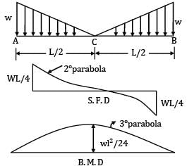
For the loaded beam as shown in the figure max B.M occurs at

Detailed Solution for Test: SFD & BMD Level - 3 - Question 6

∑Fy = 0

= wl / 2

∴ RA = wL / 4

For maximum B.M, S.F must be changes sign Maximum B.M @ c

Test: SFD & BMD Level - 3 - Question 7

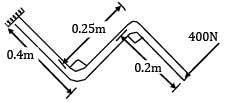
A load perpendicular to the plane of the handle is applied at the free end as shown in the given figure. The values of shear forces (S.F.), Bending Moment (B.M.) and torque at the fixed end of the handle have been determined respectively as 400N, 340Nm and 100 by a student. Among these values, those of
Detailed Solution for Test: SFD & BMD Level - 3 - Question 7
S. F = 400N and BM = 400 × (0.4 + 0.2)

= 240Nm

Torque = 400 × 0.25 = 100Nm

Test: SFD & BMD Level - 3 - Question 8

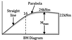
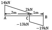
The shear force diagram of a loaded beam is shown in the following figure. The maximum bending moment of the beam is
Detailed Solution for Test: SFD & BMD Level - 3 - Question 8

15 + w x 3 = 14 + 19 = 33 ⇒ w = 6 kN/m

= 16.33

Test: SFD & BMD Level - 3 - Question 9

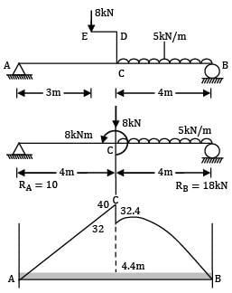
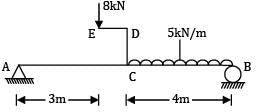
A beam AB, 8 m long hinged at end A and roller supported at end B carries a point load of 8 kN of crank ED = 1 m and uniformly distributed load of 5 kN/m over CB = 4 m. Then the bending moment where SF is zero is __________ kN-m.
Detailed Solution for Test: SFD & BMD Level - 3 - Question 9

Load of 8 kN at E is equivalent to a load 8 kN at C and a CCW moment of 8 kN at C as shown in equivalent loading diagram as shown in figure.

Reaction Moments about A

8RB + 8 = 8 × 4 + 5 × 4 × (4 + 2)

= 32 + 20 × 6 = 152

RB = 15 kN

RA = 20 + 8 − 18 = 10 kN

BM diagram

MA = 0

MC = 10 × 4 = +40 kN

MC ′ = 40 − 8 = 32 kN M6 = 10 × 6 − 8 − 8 × 2 − 5 × 2 × 1

= 60 − 8 − 16 − 10 = 26 kN/m

M8 = 0

In portion CB

Fx = 10 − 8 − (x − 4) = 0

2 − 5(x − 4) = 0

2 = 5(x − 4)

x = 4.4 m

M = bending moment where SF = 0

= 10 × 4.4 − 8(4.4 − 4) − 8 − 5(4.4 − 4)(0.2)

= 44 − 3.2 − 8 − 5(0.4)(0.2)

= 32.8 − 0.4 = 32.4 kN/m

Test: SFD & BMD Level - 3 - Question 10

A cantilever ABC, 5 m long is propped by a force of 8 kN at free end as shown in figure (a). It carries a UDL of 4 kN/m over BC = 3 m.

The point of contra-flexure is

Detailed Solution for Test: SFD & BMD Level - 3 - Question 10

Reaction at C, RC = −8 + 12 = +4 kN (upwards) ↑

SF diagram: Portion AB(x = 0 to 2 m)

FAB = +8 kN (constant)

(Taking upward forces on the left side of the section to be positive)

Portion BC (x = 2 to 5 m)

Fx = 8 − 4 (x − 2)

= 0 at x = 4 m

= −4 kN at x = 5

Figure (b) shows SF diagram.

BM diagram: Portion AB (x = 0 to 2 m)

Mx = +8x

= 0 at x = 0 m

= 16 kNm at x = 2 m

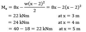
Portion BC (x = 2 to 5 m)

There is no point of contra-flexure in the cantilever.

Test: SFD & BMD Level - 3 - Question 11

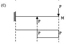
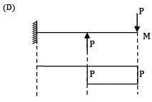
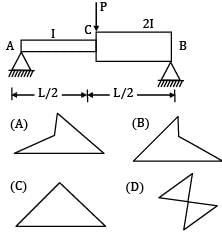
Which one of the given bending moment diagrams correctly represents that of the loaded beam shown in figure?
Option~

(A)

(B)

(C)

(D)


Detailed Solution for Test: SFD & BMD Level - 3 - Question 11
Bending moment does not depend on moment of inertia.

Test: SFD & BMD Level - 3 - Question 12

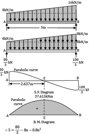
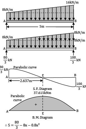
The intensity of loading on a simply supported beam of 5 meters span increases uniformly from 8 kN/m at one end to 16 kN/m at the other end. The magnitude of the maximum bending moment is __________ kN-m.

Detailed Solution for Test: SFD & BMD Level - 3 - Question 12

The trapezoidal loading on the beam consists of a uniformly distributed load and a triangular loading as shown in figure.

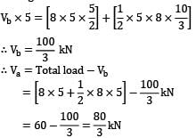
Reactions: Taking moments about the end A, we have

Consider any section XX at a distance x from A Load intensity at the section XX

= 8 +x / 5 × 8 = 8 + 1.6x

S.F. Analysis S.F. at the section XX

The S.F. diagram follows a parabolic law At x = 0, i. e. , at A

Section of Zero Shear Equating the general expression for shear force to zero,

80 / 3 − 8x − 0.8x2 = 0

∴ 3x2 + 30x − 100 = 0

Solving, we get = 2.637 m.

B.M. Analysis

B.M. at any section XX

The B.M. diagram follows a cubic law.

Maximum bending occurs at the section of zero shear, i.e., at a distance of 2.637 meters from A.

∴ Maximum bending moment

= 37.615 kNm

Test: SFD & BMD Level - 3 - Question 13

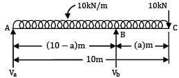
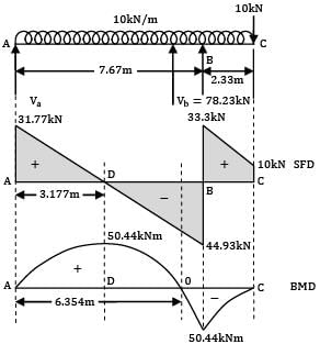
A beam of uniform section 10 metres long carries a uniformly distributed load of 10 kN per metre over the whole length and a concentrated load of 10 kN at the right end. If the beam is freely supported at the left end, then the position of the second support so that maximum bending moment for the beam shall be as small as possible is __________ m.

Detailed Solution for Test: SFD & BMD Level - 3 - Question 13

Let the supports be at A and B so that the overhang BC = a metre ∴ AB = (10 − a)metre

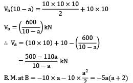
Taking moments about A,

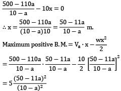
Maximum positive B.M. will occur at a section in AB. Let this section be x metres from A.

∴ S. F. at this section = 0

∴ Va − 10x = 0

For the condition that the maximum bending moment shall be as small as possible, the maximum positive bending moment and the hogging moment over the support should be numerically equal.

Solving by trial and error, we get a = 2.33 m.

Maximum B.M. with the above value of a

= 5a(a + 2)

= 5 x 2.33(2.33 + 2)

= 50.44 kNm

Figure shows the beam showing the actual position of the supports.

SF and BM diagrams

78.23 kN

Reaction at A = Va = 110 − 78.23

= 31.77 kN.

Now the SF and BM diagram can be drawn easily.

Test: SFD & BMD Level - 3 - Question 14

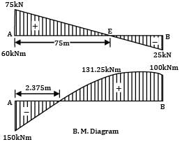
A horizontal beam is simply supported at the ends and carries a uniformly distributed load of 10 kN/m between the supports placed 10 m apart. Anticlockwise moments of 150 kNm and 100 kNm are applied to the left and right ends of the beam at the supports. The point of contra-flexure from the right hand side support is __________m

Detailed Solution for Test: SFD & BMD Level - 3 - Question 14

Taking moments about the left end A,

Vb × 10 + 100 + 150 = 10 x 10 x 5

∴ Vb = 25 kN ↑

∴ Va = (10 × 10) − 25 = 75 kN ↑

S.F. Diagram. At any section distant x from A,

the shear force is given by,

S = 75 − 10x At x = 0, S = +75 kN,

At x = 10, S = −25 kN

Section of zero shear. Equating the general expression for shear force to zero,

75 − 10x = 0

∴ x = 7.5 m

B.M. Diagram. At any section distant x from the end A the Bending Moment is given by,

M = 75x − 5x2 − 150

At x = 0, M = −150 kNm At x = 10,

M = 750 − 500 − 150 = +100 kNm

At x = 7.5 m,

Mmax = 75 × 7.5 − 5 × 7.52 − 150

= +131.25 kNm

Point of contra-flexure. Equating the general expression for B.M. to zero,

75x − 5x2 − 150 = 0x2 − 15x + 30 = 0

Solving we get x = 2.375 m.

From right hand side support = 10 − 2.375

= 7.625m

Test: SFD & BMD Level - 3 - Question 15

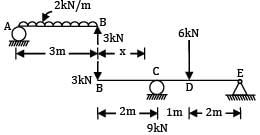
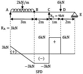
A beam AB, 3 m long is hinged at end B to another beam BCDE, 5 m long as shown in figure (a). Beam AB carries a UDL of 2 kN/m over its full length, while beam BCDE carries a point load of 6 kNm, 1 m from C at D. The maximum shear force in the beam is __________

Detailed Solution for Test: SFD & BMD Level - 3 - Question 15

Say reaction at B is RB, for beam AB this reaction will act load for beam BCDE.

Beam BCDE: Taking moments about point E.

6 x 2 + 3 x 5 = 3RC

Reaction, RC = 9 kN

Reaction, RE = 3 + 6 = 9 kN = 0 kN

Maximum shear force in the beam is 6 kN.

Test: SFD & BMD Level - 3 - Question 16

Consider the following loading condition
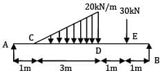
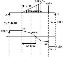
Find maximum shear force.

Detailed Solution for Test: SFD & BMD Level - 3 - Question 16

Vb x 6 = 30 × 5 + 1 / 2 x 3 x 20 x 3

Vb = 40 kN ↑

Total load applied = 30 + 1 / 2 x 3 x 20 = 60 kN

Va = 60 − 40 = 20 kN

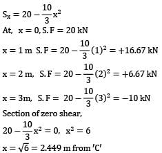
Consider any section × in CD distance x from C.

Load intensity at the section x = 20x / 3

S. F at the section X = Sx = 20 − 1 / 2x − 20x / 3

S.F at any section in DE = 30 − 40 = −10 kN

S.F at any section in EB = −40 kN

Test: SFD & BMD Level - 3 - Question 17

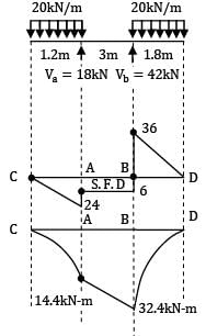
For the shown loading case the maximum bending moment will be __________

Detailed Solution for Test: SFD & BMD Level - 3 - Question 17

Vb × 3 + 20 × 1.2 × 0.6 = 20 × 1.8(3 + 0.9)

3. Vb + 14.4 = 140.4

Vb = 42 kN

Va = (20 × 1.2) + (20 × 1.8) − 42 = 18 kN

BM at C = 0

B. M at A = −20 × 1.2 × 0.6

= −14.4 kNm

BM at B = −20 × 1.8 × 0.9

= −32.4 kNm

BM at D = 0

Test: SFD & BMD Level - 3 - Question 18

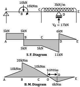
For the beam ABCDE shown in figure, the maximum bending moment is __________ kN-m.
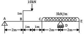
Detailed Solution for Test: SFD & BMD Level - 3 - Question 18

The 10 kN load on the bracket is transmitted to B along with a clockwise couple of

10 × 1 = 10 kNm.

Taking moments about A,

Vd × 6 = (10 × 3) + (3 × 4 × 6)

∴ Vd = 17 kN ↑ and

Va = 10 + (3 × 4) − 17 = 5 kN ↑

S.F. Analysis

S. F. at any section in AB = +5 kN

S. F. at any section in BC = +5 − 10 = −5 kN

S. F. at any section in CD,

distant x from C = S = 5 − 10 − 3x

∴ S = −5 − 3x

At x = 0, S = −5 kN, At x = 2,

S = −5 − 3 × 2 = −11 kN

S. F. at any section in DE,

distant x from E = S = 3x

At x = 0, S = 0 and at x = 2, S = +3 × 2 = +6 kN

The S. F. at D changes suddenly from

−11 kN to + 6 kN.

B. M Analysis B. M. at A= 0

B. M. on LHS of B = +5 × 2 = +10 kNm

B. M. on RHS of B = +10 + 10 = +20 kNm

B. M. at C = +5 × 4 − 10 × 2 + 10 = +10 Nm

B. M. at D = −3 × 2 × 1 = 6 kNm

B. M. at E = 0

Test: SFD & BMD Level - 3 - Question 19

SF diagram of a beam ABCD 6 m long, hinged at A and roller supported at C, is shown in figure. The distance of the point of contra-flexure from the left support is __________.

Detailed Solution for Test: SFD & BMD Level - 3 - Question 19

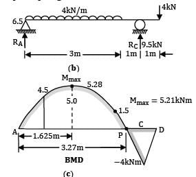
From SF diagram Reaction at A, RA = 6.5 kN ↑

Reaction at C, RC = 5.5 + 4 = 9.5 kN ↑

Over AB = 3 m

Overhang, CD = 1 m

Load at point, D = 4.0 kN ↓

Fig. (b) shows the loading diagram of the beam.

BM diagram

Position AB(x = 0 − 3 m)

M max.

SF in portion AB,

6.5 − 4(x) = 0 = SF

x = 1.625 m

Mmax = 6.5 × 1.625 − 2 × 1.6252

= 10.5625 − 5.28125

= 5.28 kNm

Point of contra-flexure Less in portion BC,

Mx = 6.5x − 4 × 3(x − 1.5)

Note that CG of UDL lies at 1.5 m from A

6.5x − 12(x − 1.5) = 0

6.5x − 12x + 18 = 0

18 = 5.5x

x = 3.27 m

Fig (c) shown BMD of the beam.

Test: SFD & BMD Level - 3 - Question 20

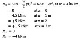
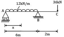
A beam ABC of segmental length AB=6m and BC = 2 m carries uniformly distributed load of intensity 12kN/m on AB and a point load of 36kN at C. Assuming simple supports at A and B, the point of contra flexure can be located at a section ___________m to the right of support A.

Detailed Solution for Test: SFD & BMD Level - 3 - Question 20

RA + RB = 12 × 6 + 36 = 108kN

Taking moment about A

RB = 84kN, RA = 24kN

B.M @ section XX is zero

⇒ x = 4m

37 videos|39 docs|45 tests
Information about Test: SFD & BMD Level - 3 Page
In this test you can find the Exam questions for Test: SFD & BMD Level - 3 solved & explained in the simplest way possible. Besides giving Questions and answers for Test: SFD & BMD Level - 3, EduRev gives you an ample number of Online tests for practice
Top Courses for Mechanical Engineering

37 videos|39 docs|45 tests
Download as PDF

Top Courses for Mechanical Engineering