Computer Science Engineering (CSE) Exam  >  Computer Science Engineering (CSE) Tests  >  GATE Computer Science Engineering(CSE) 2025 Mock Test Series  >  Test: Sequential Circuits- 2 - Computer Science Engineering (CSE) MCQ

Test: Sequential Circuits- 2 - Computer Science Engineering (CSE) MCQ


Test Description

15 Questions MCQ Test GATE Computer Science Engineering(CSE) 2025 Mock Test Series - Test: Sequential Circuits- 2

Test: Sequential Circuits- 2 for Computer Science Engineering (CSE) 2024 is part of GATE Computer Science Engineering(CSE) 2025 Mock Test Series preparation. The Test: Sequential Circuits- 2 questions and answers have been prepared according to the Computer Science Engineering (CSE) exam syllabus.The Test: Sequential Circuits- 2 MCQs are made for Computer Science Engineering (CSE) 2024 Exam. Find important definitions, questions, notes, meanings, examples, exercises, MCQs and online tests for Test: Sequential Circuits- 2 below.
Solutions of Test: Sequential Circuits- 2 questions in English are available as part of our GATE Computer Science Engineering(CSE) 2025 Mock Test Series for Computer Science Engineering (CSE) & Test: Sequential Circuits- 2 solutions in Hindi for GATE Computer Science Engineering(CSE) 2025 Mock Test Series course. Download more important topics, notes, lectures and mock test series for Computer Science Engineering (CSE) Exam by signing up for free. Attempt Test: Sequential Circuits- 2 | 15 questions in 45 minutes | Mock test for Computer Science Engineering (CSE) preparation | Free important questions MCQ to study GATE Computer Science Engineering(CSE) 2025 Mock Test Series for Computer Science Engineering (CSE) Exam | Download free PDF with solutions
Test: Sequential Circuits- 2 - Question 1


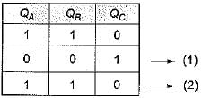
If the initial state QA QB QC = 110, after how many clocks it get back same value

Detailed Solution for Test: Sequential Circuits- 2 - Question 1

Test: Sequential Circuits- 2 - Question 2


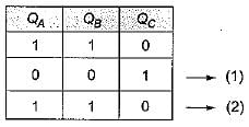
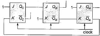
What will be the current state after two clock pulses further from the number of pulses obtained from the above question?

Detailed Solution for Test: Sequential Circuits- 2 - Question 2

1 Crore+ students have signed up on EduRev. Have you? Download the App
Test: Sequential Circuits- 2 - Question 3

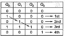
The divide by N counter as shown in figure. If initially Q0 = 0, Q1 = 1, Q2 = 0. What is the value of N?

Detailed Solution for Test: Sequential Circuits- 2 - Question 3


So 5-mod counter.

Test: Sequential Circuits- 2 - Question 4

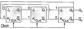
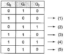
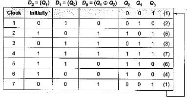
​Consider the circuit given below with initial state Q0 = 1; Q1 = Q2 = 0. The state of the circuit is given by the value 4Q2 + 2Q1 + Q

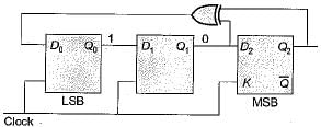
Which one of the following is the. correct state sequence of the circuit?

Detailed Solution for Test: Sequential Circuits- 2 - Question 4


Therefore, the correct state sequence of the circuit is 1, 2, 5, 3, 7, 6, 4.

Test: Sequential Circuits- 2 - Question 5

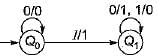
The following diagram represents a finite state machine which takes as input a binary number from the least significant bit 

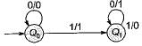
Which one of the following is TRUE?

Detailed Solution for Test: Sequential Circuits- 2 - Question 5


Here, for state Q0
When input is 0 output is 0 and it remains in state Q0.
When input is 1 output is 1 and goes to state Q1.
For state Q1.
When input is 0 output is 1, when input is 1 output is 0.
Here state changes from Q0 to Q1 when there is a 1 as input, in state Q1 every input is complemented.
Hence, the given circuit computes 2’s complement of the input number.
Hence (b) is correct answer.

Test: Sequential Circuits- 2 - Question 6

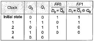
Consider the following circuit

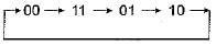
The flip-flops are positive edge triggered DFFs. Each state is designated as a two bit string Q0Q1 Let the initial state be 00. The state transition sequence is:

Detailed Solution for Test: Sequential Circuits- 2 - Question 6


The state transitions sequence is

Test: Sequential Circuits- 2 - Question 7

The functional difference between SR flip-flop and JK flip-flop is that JK flip-flop

Detailed Solution for Test: Sequential Circuits- 2 - Question 7

S-R flip flop gives invalid output when both inputs are 1 while JK flip-flop toggle the previous output when both inputs are 1. Hence it accepts both inputs 1.

Test: Sequential Circuits- 2 - Question 8

The number of flip-flops required in a modulo N counter is

Detailed Solution for Test: Sequential Circuits- 2 - Question 8

The number of flip-flops required for modulo N counter is [ log2(N)].

Test: Sequential Circuits- 2 - Question 9

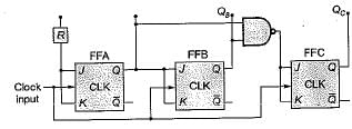
Consider the figure given below:

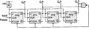
​Initially all flip-flops are cleared. How many dock pulse have to be applied to the system before the output from FF3 becomes a HIGH level?

Detailed Solution for Test: Sequential Circuits- 2 - Question 9


So 4 clock pulses are needed.

Test: Sequential Circuits- 2 - Question 10

​The logic circuit shown below is a 3-bit

Detailed Solution for Test: Sequential Circuits- 2 - Question 10

If input initially are QAQBQC = 000
So after 1st clock pulse QAQBQC = 100
Since, values is incremented so a binary up counter, synchronous since clock provided to all at same time.

Test: Sequential Circuits- 2 - Question 11

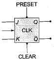
The inputs of the J-K flip-flop, shown below are:
PRESET = CLEAR = 1; J = K = 0
If a single clock pulse is applied the device will

Detailed Solution for Test: Sequential Circuits- 2 - Question 11

To make flip-flop working both preset = apart = 1 Since J = K = 0, so it does not change its state i.e. remains in same state.

Test: Sequential Circuits- 2 - Question 12

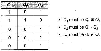
Consider the following control circuit which contains a 3-bit register and a black box with some combinational logic

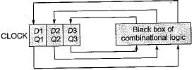
The initial state of the circuit is Q1 Q2 Q3 = 000.
The circuit generates the control sequence.
(010) → ( 110) → ( 001) →(001) → . . . → ( 001)
On successive clock cycles. Which of the following sets of equations are implemented by the combinational logic in the black box?

Detailed Solution for Test: Sequential Circuits- 2 - Question 12

Test: Sequential Circuits- 2 - Question 13

‘n’ flip-flop will divide the clock frequency by a factor of

Detailed Solution for Test: Sequential Circuits- 2 - Question 13

n-fiip-flop divide the clock frequency by a factor of 2n.

Test: Sequential Circuits- 2 - Question 14

Let an an-1 ... a1 a0 be the binary representation of an integer b. The integer b is divisible by 3 if

Detailed Solution for Test: Sequential Circuits- 2 - Question 14

Binary representation of 12 is 110 D
So, (q0 + q2)-{q1 + q3)
= (0 + 1)- ( 0 + 1) 
= 1 - 1 
= 0
0 is divisible by 3 so, true.

Test: Sequential Circuits- 2 - Question 15

If a clock with time period 'T' is used with n stage shift register, the output of final stage will be delayed by

Detailed Solution for Test: Sequential Circuits- 2 - Question 15

N stage shift register will take (n - 1) x clock time to show the output of final stage.

55 docs|215 tests
Information about Test: Sequential Circuits- 2 Page
In this test you can find the Exam questions for Test: Sequential Circuits- 2 solved & explained in the simplest way possible. Besides giving Questions and answers for Test: Sequential Circuits- 2, EduRev gives you an ample number of Online tests for practice

Top Courses for Computer Science Engineering (CSE)

Download as PDF

Top Courses for Computer Science Engineering (CSE)