Electronics and Communication Engineering (ECE) Exam  >  Electronics and Communication Engineering (ECE) Tests  >  Digital Circuits  >  Test: Sequential Logic Circuit in Digital Circuit - Electronics and Communication Engineering (ECE) MCQ

Test: Sequential Logic Circuit in Digital Circuit - Electronics and Communication Engineering (ECE) MCQ


Test Description

10 Questions MCQ Test Digital Circuits - Test: Sequential Logic Circuit in Digital Circuit

Test: Sequential Logic Circuit in Digital Circuit for Electronics and Communication Engineering (ECE) 2024 is part of Digital Circuits preparation. The Test: Sequential Logic Circuit in Digital Circuit questions and answers have been prepared according to the Electronics and Communication Engineering (ECE) exam syllabus.The Test: Sequential Logic Circuit in Digital Circuit MCQs are made for Electronics and Communication Engineering (ECE) 2024 Exam. Find important definitions, questions, notes, meanings, examples, exercises, MCQs and online tests for Test: Sequential Logic Circuit in Digital Circuit below.
Solutions of Test: Sequential Logic Circuit in Digital Circuit questions in English are available as part of our Digital Circuits for Electronics and Communication Engineering (ECE) & Test: Sequential Logic Circuit in Digital Circuit solutions in Hindi for Digital Circuits course. Download more important topics, notes, lectures and mock test series for Electronics and Communication Engineering (ECE) Exam by signing up for free. Attempt Test: Sequential Logic Circuit in Digital Circuit | 10 questions in 30 minutes | Mock test for Electronics and Communication Engineering (ECE) preparation | Free important questions MCQ to study Digital Circuits for Electronics and Communication Engineering (ECE) Exam | Download free PDF with solutions
Test: Sequential Logic Circuit in Digital Circuit - Question 1

Read the following paragraph and answer the questions.
A digital counter is a set of flipflops whose states change in response to the pulses applied at Input. Counters can be asynchronous counters or synchronous counters. A counter is an example of a state machine; the number of states is called the modulus. Two basic types of state machines are the Moore and the Mealy. In Moore machine, the combinational logic is a gate array with outputs that determine the next state of the flip-flops in the memory. For Mealy machine, the present state affects just as in Moore machine but in addition, the inputs also affect the outputs.

Q. Which of the following statements is not correct about Glitch?

Detailed Solution for Test: Sequential Logic Circuit in Digital Circuit - Question 1
  1. Strobing is a technique used to minimize or eliminate glitches in a digital system. It involves sending out a series of pulses, known as strobes, which are used to synchronize the operation of two or more digital devices.
  2. By sending out a series of strobes, the digital system can ensure that all components of the system are in sync and operating correctly. This technique can be used to eliminate glitches caused by an incorrect or out of sync signal, as well as to reduce the risk of a data loss due to a system crash.
  3. Strobing can also be used to improve the overall performance of a digital system by ensuring that the data is handled in an efficient manner.
  4. Synchronous counters are more prone to glitches than asynchronous counters because the logic in a synchronous counter is more complex and relies on precise timing. Asynchronous counters are simpler in design and do not require the same precision in timing. Therefore, they are less likely to experience glitches.
  5. Glitches can be a major issue for digital circuits and can lead to unpredictable and unexpected behavior. Glitches can occur due to a variety of causes, such as noise, slow transition times, and improper circuit design.
  6. It is important for designers to properly design digital circuits to ensure that glitches are minimized or eliminated.
  7. A glitch is an unexpected and usually short-lived fault in a system, such as a transient fault that corrects itself, or an error in a program that causes it to freeze or crash.

Hence option 3 is correct.

Test: Sequential Logic Circuit in Digital Circuit - Question 2

Choose the correct statement.

Detailed Solution for Test: Sequential Logic Circuit in Digital Circuit - Question 2

Moore Machine: In this automata, all the output symbols are associated with each state of finite state machine.
Specifications of Moore Machine:
 is a 6-tuple notation, where 

  • Q= set of finite states
  • Σ= contains finite number of input symbols. Also called Input Alphabet.
  • Δ= contains finite number of output symbols. Also called Output Alphabet.
  • δ= it is a transition function. δ:Q×Σ→Q
  • λ = it is the output function. Output is associate with only state, λ:Q→Δ
  • q0 = it represents the initial state. q0 ∈ Q

Mealy Machine: In this automata, all the output symbols are associated with transition state and transition input of the finite state machine.
Specifications of Mealy Machine:

Important Points:

  • Mealy and Moore Machines are 6-tuple notation automata.
  • The only difference between them is in their Output Function.
  • Moore Machine's output is associated with the state.
  • Mealy Machine's output is associated with the state and input.

Hence the correct answer is option 3.

1 Crore+ students have signed up on EduRev. Have you? Download the App
Test: Sequential Logic Circuit in Digital Circuit - Question 3

Comprehension:
Read the following paragraph and answer the questions.
A digital counter is a set of flipflops whose states change in response to the pulses applied at Input. Counters can be asynchronous counters or synchronous counters. A counter is an example of a state machine; the number of states is called the modulus. Two basic types of state machines are the Moore and the Mealy. In Moore machine, the combinational logic is a gate array with outputs that determine the next state of the flip-flops in the memory. For Mealy machine, the present state affects just as in Moore machine but in addition, the inputs also affect the outputs.

Q. Which of the following statements is correct about counter?

Detailed Solution for Test: Sequential Logic Circuit in Digital Circuit - Question 3
  • Design and implementation of asynchronous counter becomes tedious and complex as number of states increases.  Asynchronous counters are prone to race conditions and glitches which can lead to errors in the outputs.
  • As the number of states increases, the complexity of the counter design increases and the chances for errors also increases.
  • As the number of states increases, the design and implementation of asynchronous counters become more complex and tedious. This is because the circuitry required to implement an asynchronous counter needs to be designed in such a way as to ensure that the state transitions only occur in the correct order.
  • This requires careful consideration of the logic and design of the counter and also the timing of the signals being used to control the state transitions. As the number of states increases, the complexity of this process increases.
  •  Asynchronous counters are more complex to design and debug than synchronous counters, as the timing of each stage of the counter must be taken into account.
  • Asynchronous counters also require more logic elements than synchronous counters, making them more expensive and less efficient.
  • Asynchronous counters are also prone to glitches, in which the output changes momentarily due to the asynchronous nature of the counter.
  • Synchronous counters are digital circuits that count in a particular sequence based on the clock signal applied to them. They have a series of flip-flops connected in a chain, and the output of each flip-flop is connected to the clock input of the next flip-flop in the chain.
  • When the clock signal is applied, the first flip-flop toggles its output, which then triggers the next flip-flop to toggle its output. This process continues until the last flip-flop in the chain toggles its output. The output of each flip-flop in the chain is combined to form the count value, which can be used to represent the number of clock pulses that have passed.
  • A full modulus counter is a type of counter in which the maximum number of states can be changed. It is a digital circuit that counts from 0 to a maximum count value, then resets to 0 and continues the cycle.
Test: Sequential Logic Circuit in Digital Circuit - Question 4

Comprehension:
Read the following paragraph and answer the questions.
A digital counter is a set of flipflops whose states change in response to the pulses applied at Input. Counters can be asynchronous counters or synchronous counters. A counter is an example of a state machine; the number of states is called the modulus. Two basic types of state machines are the Moore and the Mealy. In Moore machine, the combinational logic is a gate array with outputs that determine the next state of the flip-flops in the memory. For Mealy machine, the present state affects just as in Moore machine but in addition, the inputs also affect the outputs.
In a 4-bit asynchronous binary counter, each D flip-flop is negative edge-triggered and has a propagation delay for 10 nanoseconds. What is the highest frequency allowed for the counter to avoid problems due to propagation delay?

Detailed Solution for Test: Sequential Logic Circuit in Digital Circuit - Question 4

D flip-flop is a type of flip-flop which uses two inputs, D (data) and a clock signal, to determine its output.
The output of a D flip-flop is the same as its input, D, when the clock signal is "low". When the clock signal is "high", the output of the flip-flop is the inverse of the logic level on the D input.
negative edge-triggered D flip-flop is triggered when the clock signal goes from a high to a low state, thus causing the output of the flip-flop to change.
An asynchronous binary counter is a type of digital counter that is designed to count in binary sequences, but is not synchronized to an external clock source.
Unlike synchronous binary counters, asynchronous binary counters are not dependent on the clock and can change their output states at any point in time.
Asynchronous binary counters are most commonly used in applications that require a long sequence of counting with a wide range of timing options.
Propagation delay time in a flip flop is the time it takes for the output signal to change in response to a change in the input signal. It is determined by the speed of the flip flop circuit and is typically measured in nanoseconds.
Propagation delay time = 4×10ns =40ns
The maximum clock frequency can be calculated using total propagation delay time: 1/tp.
= (1/40)ns
= 25 MHz
Hence Option 3 is correct.

Test: Sequential Logic Circuit in Digital Circuit - Question 5

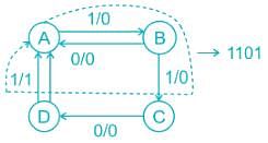
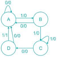
The sequence detected by the state diagram shown below is
Detailed Solution for Test: Sequential Logic Circuit in Digital Circuit - Question 5

To detect the sequence see only those i/p by which we can move in the forward direction.

Overlap/Non-Overlap:
We need to see the last state, after reaching the last state if we use bits of sequence then this will be overlapping, if we directly go to the initial state without using any bit then it will be non-overlapping.
In the question, we can see that at the last we will get sequence 1101101, 
we can use one bit in overlapping, but here we didn't use any bit of the previous detected sequence for detection of the next sequence so it is a non-overlapping type.

Test: Sequential Logic Circuit in Digital Circuit - Question 6

Read the following paragraph and answer the questions.
A digital counter is a set of flipflops whose states change in response to the pulses applied at Input. Counters can be asynchronous counters or synchronous counters. A counter is an example of a state machine; the number of states is called the modulus. Two basic types of state machines are the Moore and the Mealy. In Moore machine, the combinational logic is a gate array with outputs that determine the next state of the flip-flops in the memory. For Mealy machine, the present state affects just as in Moore machine but in addition, the inputs also affect the outputs.

Q. A binary ripple counter is required to count upto 16, 38310. If the clock frequency is 8.192 MHz, the number of flip-flops required and frequency of the output of MSB respectively are

Detailed Solution for Test: Sequential Logic Circuit in Digital Circuit - Question 6

binary ripple counter is a type of counter in which the output of one flip-flop is connected to the clock input of the next flip-flop.
This causes the output of the counter to ripple from one flip-flop to the next, creating a series of pulses. The output of the counter can be used to drive a digital display, such as a 7-segment display, to show the binary count.
In a counter, Number of flip flop = log2 N
where, N is Max count value.
Number of flip flops required = log(16383)= 14
In this case, we need to count up to 16,383 (in binary 111111111111111). This requires 14 flip-flops, as the number of bits required to represent the number 16,383 is 14.
The frequency of the output of the MSB  is given as : FCLK/N
where,
FCLK  is clock frequency
N is Max count value
so MSB frequency = 
= 500Hz
Hence correct option is 4.

Test: Sequential Logic Circuit in Digital Circuit - Question 7

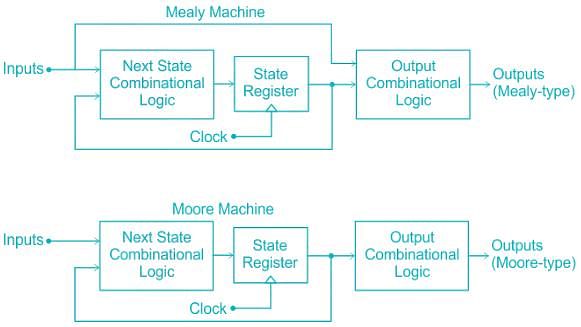
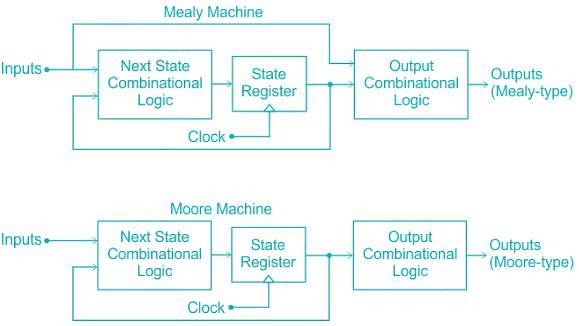
A finite state machine in which

  1. the output is a function of the current state and Inputs
  2. the output is a function of only the current state

Q. Which of the following machines is respectively correct for these styles?

Detailed Solution for Test: Sequential Logic Circuit in Digital Circuit - Question 7

The block diagram explanation of Mealy and Moore machine are as shown:

Test: Sequential Logic Circuit in Digital Circuit - Question 8

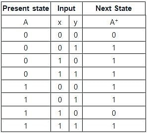
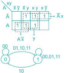
The following state diagram represents which of the input equation. (Given : DA = [A, x, y]) (Where DA denotes a DFF with output A. The x and y are the inputs to the circuit)

Detailed Solution for Test: Sequential Logic Circuit in Digital Circuit - Question 8

DA [A, x, y] → DA denotes DA – flip flop with output x, y are inputs.


When A = 0: xy = 0 0 → A+ = 0
0 1 → A+ = 1
1 0 → A+ = 1
1 1 → A+ = 1
When A = 1   xy = 0 0 → 1
0 1 →  1
0 1 → 1
1 0 → 0
1 1 → 1
A+ = y + Ax̅ + A̅x
DA = A+ = y + A ⊕ x = A ⊕ x + y

Test: Sequential Logic Circuit in Digital Circuit - Question 9

The number of directed arcs terminating on any state of a state diagram is

Detailed Solution for Test: Sequential Logic Circuit in Digital Circuit - Question 9

The number of directed arcs terminating on any state of a state diagram is independent of the number of inputs.
Explanation:

  • The output of the Mealy machine is a function of the present state as well as present input, so the output does not remain stable over the entire clock.
  • The outputs of a Mealy Machine can change asynchronously in response to any change in the inputs.
  • The disadvantage associated with the circuit is that if any input transient glitches are present, they are directly conveyed to the output.
  • The output need not change at a Clock Pulse.
  • It requires less number of states and thereby less hardware to solve any problem.

The block diagram explanation of the Mealy and Moore machine are as shown:

Test: Sequential Logic Circuit in Digital Circuit - Question 10

Which of the following is true in case of Moore Machine?

Detailed Solution for Test: Sequential Logic Circuit in Digital Circuit - Question 10

Moore Machine:
Moore machine is defined as a machine in the theory of computation whose output values are determined only by its current state.
Characteristics of Moore Machine:

  1. The output depends only upon the present state. 
  2. The output is likely to change with clock transition.
  3. It requires more number of states to implement a function.
  4. Input changes do not affect the output.
  5. There is less hardware requirement for circuit implementation. 
  6. They react slower to clock pulses.
6 videos|76 docs|52 tests
Information about Test: Sequential Logic Circuit in Digital Circuit Page
In this test you can find the Exam questions for Test: Sequential Logic Circuit in Digital Circuit solved & explained in the simplest way possible. Besides giving Questions and answers for Test: Sequential Logic Circuit in Digital Circuit, EduRev gives you an ample number of Online tests for practice

Top Courses for Electronics and Communication Engineering (ECE)

6 videos|76 docs|52 tests
Download as PDF

Top Courses for Electronics and Communication Engineering (ECE)