Civil Engineering (CE) Exam  >  Civil Engineering (CE) Tests  >  GATE Civil Engineering (CE) 2025 Mock Test Series  >  Test: Solid Mechanics- 2 - Civil Engineering (CE) MCQ

Test: Solid Mechanics- 2 - Civil Engineering (CE) MCQ


Test Description

10 Questions MCQ Test GATE Civil Engineering (CE) 2025 Mock Test Series - Test: Solid Mechanics- 2

Test: Solid Mechanics- 2 for Civil Engineering (CE) 2024 is part of GATE Civil Engineering (CE) 2025 Mock Test Series preparation. The Test: Solid Mechanics- 2 questions and answers have been prepared according to the Civil Engineering (CE) exam syllabus.The Test: Solid Mechanics- 2 MCQs are made for Civil Engineering (CE) 2024 Exam. Find important definitions, questions, notes, meanings, examples, exercises, MCQs and online tests for Test: Solid Mechanics- 2 below.
Solutions of Test: Solid Mechanics- 2 questions in English are available as part of our GATE Civil Engineering (CE) 2025 Mock Test Series for Civil Engineering (CE) & Test: Solid Mechanics- 2 solutions in Hindi for GATE Civil Engineering (CE) 2025 Mock Test Series course. Download more important topics, notes, lectures and mock test series for Civil Engineering (CE) Exam by signing up for free. Attempt Test: Solid Mechanics- 2 | 10 questions in 30 minutes | Mock test for Civil Engineering (CE) preparation | Free important questions MCQ to study GATE Civil Engineering (CE) 2025 Mock Test Series for Civil Engineering (CE) Exam | Download free PDF with solutions
Test: Solid Mechanics- 2 - Question 1

The shear stress at the centre of a circular shaft under torsion is

Detailed Solution for Test: Solid Mechanics- 2 - Question 1

The simple torsion equation is written as

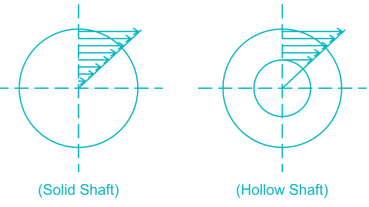
This states that the shearing stress varies directly as the distance ‘r' from the axis of the shaft and the following is the stress distribution

Hence the maximum shear stress occurs on the outer surface of the shaft where r = R and at the centre the shear stress is zero.

Test: Solid Mechanics- 2 - Question 2

Match List-I with List-II and select the correct answer using the code given below the lists.

List-I (Loaded Beam)

A.


B.


C.
 

List-II (Maximum Bending moment)
1. 
2. 
3. 
4. 

Detailed Solution for Test: Solid Mechanics- 2 - Question 2

A-3, B-1, C-4

Beam A is cantilever so maximum bending moment occurs at the fixed support

Beam B is simply supported so maximum bending moment occurs at midspan

Beam C is cantilever so maximum bending moment occurs at fixed support
MC

1 Crore+ students have signed up on EduRev. Have you? Download the App
Test: Solid Mechanics- 2 - Question 3

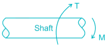
A solid circular shaft of diameter d is subjected to a combined effect of bending moment M and torque T. The relation is used  for designing the shaft using which one of this material property

Detailed Solution for Test: Solid Mechanics- 2 - Question 3


Ssy = Torsional yield strength

Test: Solid Mechanics- 2 - Question 4

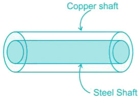
A solid steel shaft is surrounded by a copper shaft, such that, Isteel = 1/2 Icopper. If Gcopper = 1/2 Gsteel, what is the ratio of Ts/Tc if the composite shaft is subjected to a twisting moment?

Detailed Solution for Test: Solid Mechanics- 2 - Question 4


Both shaft will rotate through same degree.

Hence 

Test: Solid Mechanics- 2 - Question 5

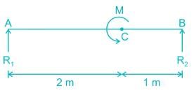
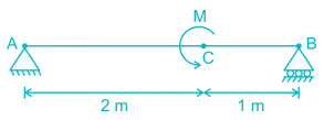
Couple M is applied at C on a simply supported beam AB. The maximum shear force on AC will be
Detailed Solution for Test: Solid Mechanics- 2 - Question 5


R1 + R2 = 0

∑MA = 0

⇒ R2 × 3 = -M


So maximum shear force = M/3

Test: Solid Mechanics- 2 - Question 6

A hollow steel shaft of external diameter 100 mm and internal diameter 50 mm is to be replaced by a solid allow shaft. Assuming the same value of polar modulus for both, the diameter of the solid allows shaft will be-

Detailed Solution for Test: Solid Mechanics- 2 - Question 6

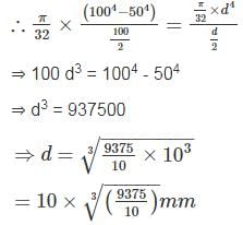
Polar modulus, 

Let the diameter of solid shaft is ‘d’

*Answer can only contain numeric values
Test: Solid Mechanics- 2 - Question 7

For a loaded cantilever beam of uniform cross-section, the bending moment (in N-mm) along the length is M(x) = 5x2 + 10x, where x is the distance (in mm) measured from the free end of the beam. The magnitude of shear force (in N) in the cross-section at x = 10 mm is ________.


Detailed Solution for Test: Solid Mechanics- 2 - Question 7

M = 5x2 + 10x

Shear Force = dM/dx = 10x + 10

Shear force at X = 10 mm

= 10 x 10 + 10 = 110 N

Test: Solid Mechanics- 2 - Question 8

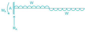
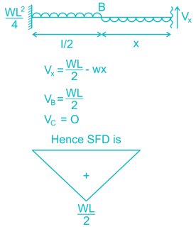
S.F.D for the beam is:

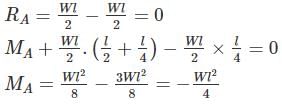
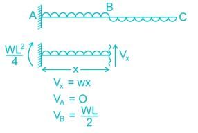
Detailed Solution for Test: Solid Mechanics- 2 - Question 8


Test: Solid Mechanics- 2 - Question 9

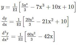
The equation for the deflected shape of a beam carrying a U.D.L and simply supported at ends is given below  The load carrying capacity of the beam is

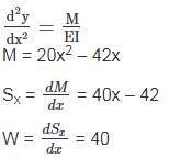
Detailed Solution for Test: Solid Mechanics- 2 - Question 9


Using the equation of deflection:

W = 40 kN/m

*Answer can only contain numeric values
Test: Solid Mechanics- 2 - Question 10

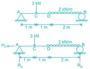
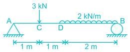
For the given figure, calculate the bending moment (in kN-m) at 2 m from the left end?

Detailed Solution for Test: Solid Mechanics- 2 - Question 10


∑FV = 0

RA + RB = 3 + 2 × 2

RA + RB = 7 kN

∑FH = 0

HA = 0

∑Mz = 0

RA × 4 – 3 × 3 - 2 × 2 × 1= 0

RA = 3.25 kN

RB = 3.75 kN

BMD = R× 2 - 3 × 1

BMD = 3.25 × 2 - 3 = 3.5 kN

31 docs|280 tests
Information about Test: Solid Mechanics- 2 Page
In this test you can find the Exam questions for Test: Solid Mechanics- 2 solved & explained in the simplest way possible. Besides giving Questions and answers for Test: Solid Mechanics- 2, EduRev gives you an ample number of Online tests for practice

Top Courses for Civil Engineering (CE)

Download as PDF

Top Courses for Civil Engineering (CE)