Steady State Time Domain Analysis of Type-A Chopper - Free MCQ Practice
MCQ Practice Test & Solutions: Test: Steady State Time Domain Analysis of Type-A Chopper (5 Questions)
You can prepare effectively for Electrical Engineering (EE) Power Electronics with this dedicated MCQ Practice Test (available with solutions) on the important topic of "Test: Steady State Time Domain Analysis of Type-A Chopper". These 5 questions have been designed by the experts with the latest curriculum of Electrical Engineering (EE) 2026, to help you master the concept.
Test Highlights:
- - Format: Multiple Choice Questions (MCQ)
- - Duration: 15 minutes
- - Number of Questions: 5
Sign up on EduRev for free to attempt this test and track your preparation progress.

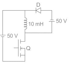
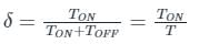
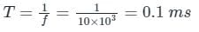
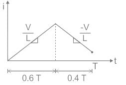
In the dc-dc converter circuit shown, switch Q is switched at a frequency of 10 kHz with a duty ratio of 0.6. All components of the circuit are ideal, and the initial current in the inductor is zero. Energy stored in the inductor in mJ (rounded off to 2 decimal places) at the end of 10 complete switching cycles is ________
Detailed Solution: Question 1


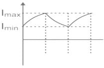
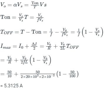
For the circuit shown in the figure, assume L to be large enough to ensure linear growth and decay of the current through it and have continuous current. The maximum value of the load current in amperes is _________ (Vs = 100 V, Vo = 50 V, L = 2mH, f = 20 kHz, R = 10 Ω)
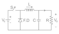
Detailed Solution: Question 2


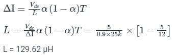
In the circuit shown below, if load R = 500 Ω, switching frequency is 25 kHz and peak to peak ripple current of inductor is limited to 0.9 A then the filter inductance L is

Detailed Solution: Question 3
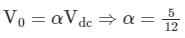
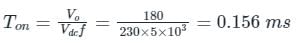
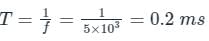
In chopper circuit the average value of output voltage is controlled by time ratio control (TRC) method. The chopper is operated at a frequency of 5kHz on a 230 V d.c. supply. If the load voltage is 180 V, then the blocking period of thyristor in each cycle is___(in μsec)
Detailed Solution: Question 4
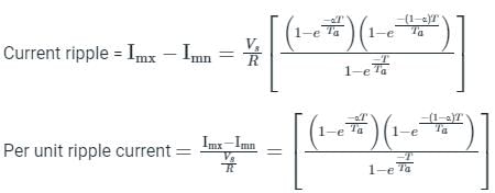
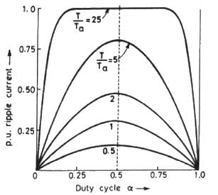
A dc chopper is fed from constant voltage mains. The duty ratio α of the chopper is progressively increased while the chopper feeds RL load. The per unit current ripple would
Detailed Solution: Question 5
5 videos|78 docs|46 tests |