Electrical Engineering (EE) Exam  >  Electrical Engineering (EE) Test  >  Analog and Digital Electronics  >  Test: The Common Emitter Configuration - Electrical Engineering (EE) MCQ

The Common Emitter Configuration - Free MCQ Practice Test with solutions,


MCQ Practice Test & Solutions: Test: The Common Emitter Configuration (10 Questions)

You can prepare effectively for Electrical Engineering (EE) Analog and Digital Electronics with this dedicated MCQ Practice Test (available with solutions) on the important topic of "Test: The Common Emitter Configuration". These 10 questions have been designed by the experts with the latest curriculum of Electrical Engineering (EE) 2026, to help you master the concept.

Test Highlights:

  • - Format: Multiple Choice Questions (MCQ)
  • - Duration: 10 minutes
  • - Number of Questions: 10

Sign up on EduRev for free to attempt this test and track your preparation progress.

Test: The Common Emitter Configuration - Question 1

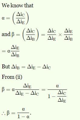
The base current amplification factor β is given by_________

Detailed Solution: Question 1

The current amplification factor (β) is given by IC//IB. When no signal is applied, then the ratio of collector current to the base current is called current amplification factor of a transistor.

Test: The Common Emitter Configuration - Question 2

In an NPN silicon transistor, α=0.995, IE=10mA and leakage current ICBO=0.5µA. Determine ICEO.

Detailed Solution: Question 2

 IC=α IE +ICBO =0.995*10mA+0.5µA=9.9505mA.
IB=IE-IC=10-9.9505=0.0495mA. β=α/(1-α)=0.995/(1-0.995)=199
ICEO=9.9505-199*0.0495=0.1mA==100µA.

Test: The Common Emitter Configuration - Question 3

A germanium transistor with α=0.98 gives a reverse saturation current ICBO=10µA in a CB configuration. When it is used in CE configuration with a base current of 0.22µA, calculate the collector current.

Detailed Solution: Question 3

Given, ICBO=10µA, α=0.98 and IB =0.22µA. IC=α/ (1-α) IB+ 1/(1-α) ICBO
0.01078+0.5=0.51078mA.

Test: The Common Emitter Configuration - Question 4

In CE configuration, if the voltage drop across 5kΩ resistor connected in the collector circuit is 5V. Find the value of IB when β=50.

Detailed Solution: Question 4

 IC=V across RL/RL=5V/5KΩ=1mA.
IB=IC/β=1/50=0.02mA.

Test: The Common Emitter Configuration - Question 5

A transistor is connected in CE configuration. Collector supply voltage Vcc=10V, RL=800Ω, voltage drop across RL=0.8V, α=0.96. What is base current?

Detailed Solution: Question 5

Here, IC=0.8/800=1mA
β= α/ (1-α)=0.96/1-0.96=24.
Now, IB=IC/ β=1/24=41.67µA.

Test: The Common Emitter Configuration - Question 6

The collector supply voltage for a CE configured transistor is 10V. The resistance RL=800Ω. The voltage drop across RL is 0.8V. Find the value of collector emitter voltage.

Detailed Solution: Question 6

Here, IC=0.8/800=1mA.
We know, VCE=VCC-ICRL
=10-0.8=9.2V.

Test: The Common Emitter Configuration - Question 7

 The relation between α and β is_________

Detailed Solution: Question 7

Test: The Common Emitter Configuration - Question 8

In ICEO, wt does the subscript ‘CEO’ mean?

Detailed Solution: Question 8

The subscript ‘CEO’ means that it is collector to emitter base open. It is called as the leakage current. It occurs in a reverse bias in PNP transistor. The total current can be calculated by IC=βIB+IC.

Test: The Common Emitter Configuration - Question 9

When the signal is applied, the ratio of change of collector current to the ratio of change of base current is called_________

Detailed Solution: Question 9

The ac current gain is given by β=∆IC/∆IB. When the signal is applied, the ratio of change of collector current to the ratio of change of base current is called ac current gain.

Test: The Common Emitter Configuration - Question 10

 The range of β is _________

Detailed Solution: Question 10

Almost in all the transistors, the base current is less than 5% of the emitter current. Due to this fact, it is generally greater than 20. Usually it ranges from 20 to 500. Hence this configuration is frequently used when appreciable current gain as well as voltage gain is required.

135 videos|183 docs|71 tests
Information about Test: The Common Emitter Configuration Page
In this test you can find the Exam questions for Test: The Common Emitter Configuration solved & explained in the simplest way possible. Besides giving Questions and answers for Test: The Common Emitter Configuration, EduRev gives you an ample number of Online tests for practice
135 videos|183 docs|71 tests
Download as PDF