Electronics and Communication Engineering (ECE) Exam  >  Electronics and Communication Engineering (ECE) Tests  >  Analog Circuits  >  Test: Uni Junction Transistor (UJT) - Electronics and Communication Engineering (ECE) MCQ

Test: Uni Junction Transistor (UJT) - Electronics and Communication Engineering (ECE) MCQ


Test Description

15 Questions MCQ Test Analog Circuits - Test: Uni Junction Transistor (UJT)

Test: Uni Junction Transistor (UJT) for Electronics and Communication Engineering (ECE) 2024 is part of Analog Circuits preparation. The Test: Uni Junction Transistor (UJT) questions and answers have been prepared according to the Electronics and Communication Engineering (ECE) exam syllabus.The Test: Uni Junction Transistor (UJT) MCQs are made for Electronics and Communication Engineering (ECE) 2024 Exam. Find important definitions, questions, notes, meanings, examples, exercises, MCQs and online tests for Test: Uni Junction Transistor (UJT) below.
Solutions of Test: Uni Junction Transistor (UJT) questions in English are available as part of our Analog Circuits for Electronics and Communication Engineering (ECE) & Test: Uni Junction Transistor (UJT) solutions in Hindi for Analog Circuits course. Download more important topics, notes, lectures and mock test series for Electronics and Communication Engineering (ECE) Exam by signing up for free. Attempt Test: Uni Junction Transistor (UJT) | 15 questions in 45 minutes | Mock test for Electronics and Communication Engineering (ECE) preparation | Free important questions MCQ to study Analog Circuits for Electronics and Communication Engineering (ECE) Exam | Download free PDF with solutions
Test: Uni Junction Transistor (UJT) - Question 1

How many terminals are there in a unijunction transistor?

Detailed Solution for Test: Uni Junction Transistor (UJT) - Question 1

A unijunction transistor consists of three terminals. It is a semiconductor device that displays negative resistance and switching characteristics. It is used as a relaxation oscillator in phase control applications.

Test: Uni Junction Transistor (UJT) - Question 2

What is the intrinsic stand-off ratio(η) of a unijunction transistor when RB1 = 10kΩ and RBB = 15kΩ?

Detailed Solution for Test: Uni Junction Transistor (UJT) - Question 2

The intrinsic stand-off ratio(η) is equal to the ratio RB1 / RBB. Standard values of η range from 0.5 to 0.8.
Given RB1 = 10kΩ and RBB 
= 15kΩ:
η = RB1 / RBB 
= 10 / 15
= 0.67

1 Crore+ students have signed up on EduRev. Have you? Download the App
Test: Uni Junction Transistor (UJT) - Question 3

What are the terminals of a unijunction transistor?

Detailed Solution for Test: Uni Junction Transistor (UJT) - Question 3

The unijunction transistor consists of a single solid piece of N-type channel with its two outer connections marked as Base 2 and Base 1. The third connection is the Emitter and it is located along the channel. The emitter lies closer to base 2 as compared to base 1.

Test: Uni Junction Transistor (UJT) - Question 4

What are unijunction transistors used for?

Detailed Solution for Test: Uni Junction Transistor (UJT) - Question 4

Unlike bipolar transistors or field effect transistors these unijunction transistors cannot be used to amplify a circuit. The unijunction transistors are used as an on-off switching transistor. They have unidirectional conductivity.

Test: Uni Junction Transistor (UJT) - Question 5

What is the generalized value for the voltage across resistor RB1 in a unijunction transistor?

Detailed Solution for Test: Uni Junction Transistor (UJT) - Question 5

The generalized value for the voltage across resistor RB1 is (RB1 / RB1 + RB2) × VBB. Where, RB1 and RB2 are the resistance across two terminals B1 and B2. The voltage VBB is the voltage across the two terminals.

Test: Uni Junction Transistor (UJT) - Question 6

Which type of material is the channel of a unijunction transistor made up of?

Detailed Solution for Test: Uni Junction Transistor (UJT) - Question 6

The core conducting component is the N-type channel of the transistor. Unijunction transistor consists of a single solid piece of N-type semiconductor material forming the main current carrying channel.

Test: Uni Junction Transistor (UJT) - Question 7

What are the working regions of a unijunction transistor?

Detailed Solution for Test: Uni Junction Transistor (UJT) - Question 7

As soon as the transistor reaches the triggering voltage the unijunction transistor will turn on. If the applied voltage increases to the emitter lead, the peak voltage is achieved. The voltage drops from peak voltage to Valley Point. This happens in spite of the current increasing; this is because of the negative resistance.

Test: Uni Junction Transistor (UJT) - Question 8

The Programmable Unijunction Transistor (PUT) turns on & starts conducting when the

Detailed Solution for Test: Uni Junction Transistor (UJT) - Question 8

The device only starts to conduct when the forward anode to cathode voltage exceeds the applied gate to cathode voltage.

Test: Uni Junction Transistor (UJT) - Question 9

A unijunction transistor (UJT) is used to generate a ____ wave

Detailed Solution for Test: Uni Junction Transistor (UJT) - Question 9

Uni Junction Transistor (UJT):

  • The uni-junction transistor is a solid-state three-terminal device that can be used in gate pulse, timing circuits, and trigger generator applications to switch and control both thyristors and triacs for AC power control type applications.
  • When a UJT is used for triggering an SCR, the wave shape of the voltage obtained from the UJT circuit is a saw-tooth wave.
  • The UJT is a three-terminal, semiconductor device which exhibits negative resistance and switching characteristics for use as a relaxation oscillator in phase control applications.
  • The device has only one junction, so it is called the unijunction device
  • The device, because of one P-N junction, is quite similar to a diode but it differs from an ordinary diode as it has three terminals
  • The structure of a UJT is quite similar to that of an N-channel JFET
  • The main difference is that P-type (gate) material surrounds the N-type (channel) material in the case of JFET and the gate surface of the JFE T is much larger than the emitter junction of UJT
  • In a unijunction transistor, the emitter is heavily doped while the N-region is lightly doped, so the resistance between the base terminals is relatively high, typically 4 to 10 kilo Ohm when the emitter is open
  • The N-type silicon bar has a high resistance and the resistance between emitter and base1 is larger than that between emitter and base2; It is because emitter is closer to base2 than base1
  • UJT is operated with emitter junction forward- biased while the JFET is normally operated with the gate junction reverse-biased
  • UJT does not have the ability to amplify but it has the ability to control a large AC power with a small signal. So that it is not used for amplification purposes. 

Applications of UJT:

  • Uses negative oscillator resistance property for the generation of the sawtooth waveform
  • Used as a Relaxation oscillator.
  • Used as a Voltage regulator.
  • Used as a switching circuit.
  • Widely used as a triggering device for silicon control rectifiers (SCR).
  • Used as a phase control circuit.
  • Used as a timing circuit.
  • Used in a sawtooth generator.
  • Used to generate magnetic flux.
Test: Uni Junction Transistor (UJT) - Question 10

The VI characteristics of UJT is Similar to

Detailed Solution for Test: Uni Junction Transistor (UJT) - Question 10

Unipolar Junction Transistor (UJT)

A UJT is a three-terminal semiconductor switching device. This device has a unique characteristic that when it is triggered, the emitter current increases regeneratively until it is limited by the emitter power supply. Due to this characteristic, the UJT can be employed in a variety of applications e.g., switching, pulse generator, sawtooth generator etc.

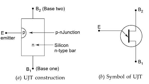
Construction: The figure shows the structure of a unijunction transistor. It consists of an n-type silicon bar with an electrical connection on each end. The leads to these connections are called base leads base. One B1 and base two B2. Partway along the bar between the two bases, nearer to B2 than B1, a p-n junction is formed between a p-type emitter and the bar. The lead to this junction is called the emitter lead E.

  • Since the device has one p-n junction and three leads, it is commonly called UJT.
  • With only one p-n junction, a device is really a form of diode because of the two bases taken from one section of the diode, the device is also called a double-based diode.
  • The emitter is heavily doped having many holes. The n-region is lightly doped.

Characteristics of UJT

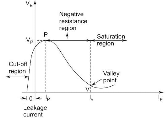
  • The figure shows the curve between emitter voltage (VE) and emitter current (IE) Of a UJT at a given voltage VBB between the bases. These is known as the emitter characteristics of UJT.
  • Initially, in the cut-off region, as VE increases from zero, slight leakage current flows from terminal B2 to the emitter. This current is due to minority carriers in the reverse-biased diode.
  • Above a certain value of VE, forward IE begins to flow, increasing until the peak voltage Vp and current Ip are reached at point P.
  • After the peak point P. an attempt to increase VE is followed by a sudden increase in emitter current IE with a corresponding decrease in VE. This is a negative resistance portion of the curve because of an increase in IE. VE decreases. The device, therefore, has a negative resistance region that is stable enough to be used with a great deal of reliability in many areas, e.g., trigger circuits, sawtooth generators, biasing circuits.
  • The negative portion of the curve lasts until valley point V is reached with valley point voltage Vv and valley-point current Iv. After the valley point, the device is driven to saturation.
Test: Uni Junction Transistor (UJT) - Question 11

UJT when used for triggering an SCR, has the waveform

Detailed Solution for Test: Uni Junction Transistor (UJT) - Question 11

UJT Relaxation Oscillator

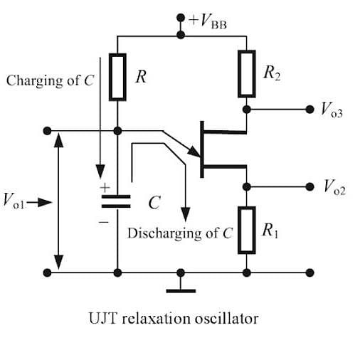
A UJT relaxation oscillator consists of a capacitor C and a resistor R connected to the emitter of the UJT, as shown in Fig. Base B2 of the UJT is connected to the power-supply positive through resistor R2, and base B1 is connected to the ground through resistor R, Usually, R1 and R2 are low-value resistors, a typical value being 47 ohms each. These are used to limit the current through the UJT and protect it. We can take three outputs from the UJT relaxation oscillator. These are Vo1, Vo2, and Vo3, respectively.

Test: Uni Junction Transistor (UJT) - Question 12

The P-side emitter in UJT is

Detailed Solution for Test: Uni Junction Transistor (UJT) - Question 12

The Unijunction transistor is 2-layer, the 3-terminal solid-state switching device (silicon). It is also called as the double-base diode. The device has a unique characteristic that when it is triggered, its emitter current increases regeneratively (due to negative resistance characteristic) until it is restricted by an emitter power supply. Since the device has one PN junction and three leads it is commonly called UJT.

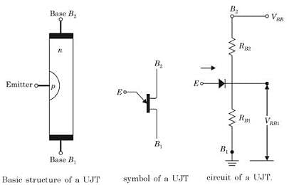
A unijunction transistor (UJT) is a three-terminal semiconductor device having one p-n junction. It is mostly used as a switch and commonly employed in timing circuits, SCR/Triac triggering circuits, oscillators, and so on. It consists of an n-type silicon semiconductor bar having ohmic contacts at each end. The two end connections are called base-1 and base-2, which are labeled as B1 and B2, respectively. This n-type semiconductor is lightly doped. Near terminal B2, a small heavily doped p-region is alloyed which forms a p-n junction with the bar. The terminal to this junction is called emitter (E). The resistance of the silicon bar is called InterBase resistance RBB, i.e. the resistance between the terminals B1 and B2.

Internally UJT acts like a voltage divider consisting of two series resistors RB1 and RB2, while the P-N junction acts like a diode D driving the junction of RB1 and RB2

Since P-region is heavily doped as compared to N-region, holes are injected from P-region to the lower half of UJT. As N-region is lightly doped the holes injected have a longer lifetime The flooding of the lower half of UJT with holes drastically lowers the resistance RB1. Because of this, the drop across RB1 reduces to a low value, and the emitter current increases. 

Test: Uni Junction Transistor (UJT) - Question 13

When emitter terminal of a UJT is open then the resistance of the base terminal is

Detailed Solution for Test: Uni Junction Transistor (UJT) - Question 13

A unijunction transistor (UJT) is a three-terminal semiconductor device having one p-n junction. It is mostly used as a switch and commonly employed in timing circuits, SCR/Triac triggering circuits, oscillators, and so on. It consists of an n-type silicon semiconductor bar having ohmic contacts at each end. The two end connections are called base-1 and base-2, which are labeled as B1 and B2, respectively. This n-type semiconductor is lightly doped. Near the terminal B2, a small heavily doped p-region is alloyed which forms a p-n junction with the bar. The terminal to this junction is called emitter (E).

The total resistance of the silicon bar from terminal B2 to B1 with emitter open is called the InterBase resistance RBB. Thus,

RBB = RB1 + RB2, with emitter open

where RBB is typically in the range of 4 kΩ to 10 kΩ and RB1 is usually greater than RB(RB2 = 60% of RBB. Hence the resistance of the base terminal is very high in UJT.

Test: Uni Junction Transistor (UJT) - Question 14

The advantages over the vacuum triode for a junction transistor is_________

Detailed Solution for Test: Uni Junction Transistor (UJT) - Question 14

A junction transistor is an analogous to a vacuum triode. The main difference between them is that a transistor is a current device while a vacuum triode is a voltage device. The advantages of a transistor over a vacuum triode are long life, high efficiency, light weight, smaller in size, less power consumption.

Test: Uni Junction Transistor (UJT) - Question 15

Which of the following is true in construction of a transistor?

Detailed Solution for Test: Uni Junction Transistor (UJT) - Question 15

In most of the transistors, the collector is made larger than emitter region. This is due to the fact that collector has to dissipate much greater power. The collector and emitter cannot be interchanged.

3 videos|33 docs|64 tests
Information about Test: Uni Junction Transistor (UJT) Page
In this test you can find the Exam questions for Test: Uni Junction Transistor (UJT) solved & explained in the simplest way possible. Besides giving Questions and answers for Test: Uni Junction Transistor (UJT), EduRev gives you an ample number of Online tests for practice

Top Courses for Electronics and Communication Engineering (ECE)

3 videos|33 docs|64 tests
Download as PDF

Top Courses for Electronics and Communication Engineering (ECE)