Analog Electronics - 4 - Free MCQ Test with solutions for GATE EE and Digital
MCQ Practice Test & Solutions: Analog Electronics - 4 (10 Questions)
You can prepare effectively for Electrical Engineering (EE) Analog and Digital Electronics with this dedicated MCQ Practice Test (available with solutions) on the important topic of "Analog Electronics - 4". These 10 questions have been designed by the experts with the latest curriculum of Electrical Engineering (EE) 2026, to help you master the concept.
Test Highlights:
- - Format: Multiple Choice Questions (MCQ)
- - Duration: 30 minutes
- - Number of Questions: 10
Sign up on EduRev for free to attempt this test and track your preparation progress.

Detailed Solution: Question 1
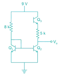
In the circuit shown below all the transistors are identical with; VBE = 0.7 V; VCE(sat) = 0.2 If the transistor Q3 is in saturation then V0 is
Detailed Solution: Question 2


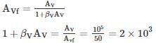
Consider series-shunt amplifier in which the open loop gain is Av = 105 and the closed loop gain is AVf = 50. Assume the input and output resistance of the basic amplifier are Ri = 10 kΩ and Ro = 20 kΩ. Determine the input resistance of series input connecting and the output resistance of a shunt output connection for an ideal feedback voltage amplifier.
Detailed Solution: Question 3
 The output resistance is
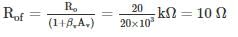
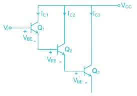
For the circuit shown in fig, the transconductance of Q1 is gm1, of Q2 is gm2 and Q3 is gm3 then the overall trans-conductance gm is
Detailed Solution: Question 4
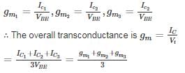
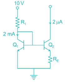
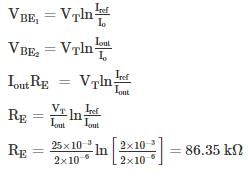
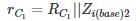
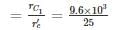
The circuit shown in figure uses matched transistor. With a thermal voltage VT = 25 mV, The value of β is very high. Find the value of emitter resistance in kΩ
Detailed Solution: Question 5
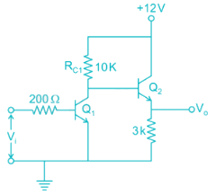
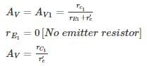
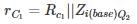
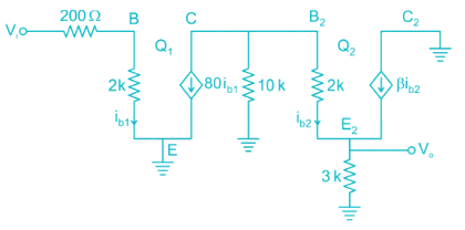
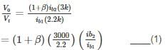
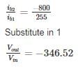
The two stages of the amplifier are shown in the figure. Both transistors have current gain β of 80 and dynamic emitter resistance r′e of 25Ω. The magnitude of the overall voltage gain of the amplifier is approximately
Detailed Solution: Question 6
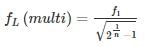
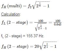
Two RC coupled amplifiers are connected to form a 2-stage amplifier. If the lower and upper cut off frequencies of each individual amplifiers is 100 Hz and 20 kHz. Then the 3-dB bandwidth of the two-state amplifier is ____ Hz.
Detailed Solution: Question 7
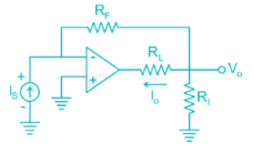
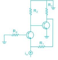
In the AC equivalent circuit shown in Fig, if Iin is the Input current and Feedback Resistance is very large, the type of Feedback
Detailed Solution: Question 8
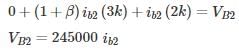
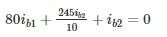
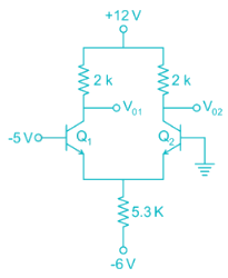
The differential DC output voltage V01 – V02 in the circuit shown is ____ V.
Detailed Solution: Question 9

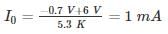
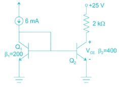
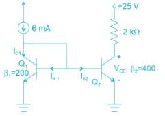
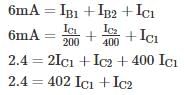
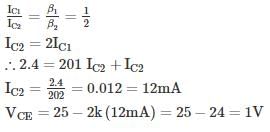
Find the value of VCE in the given figure.
Assume the base currents to be the same.
Assume the base currents to be the same.
Detailed Solution: Question 10
135 videos|183 docs|71 tests |