Test: 555 Timer - Electronics and Communication Engineering (ECE) MCQ


Test Description

10 Questions MCQ Test GATE ECE (Electronics) Mock Test Series 2025 - Test: 555 Timer

Test: 555 Timer for Electronics and Communication Engineering (ECE) 2025 is part of GATE ECE (Electronics) Mock Test Series 2025 preparation. The Test: 555 Timer questions and answers have been prepared according to the Electronics and Communication Engineering (ECE) exam syllabus.The Test: 555 Timer MCQs are made for Electronics and Communication Engineering (ECE) 2025 Exam. Find important definitions, questions, notes, meanings, examples, exercises, MCQs and online tests for Test: 555 Timer below.
Solutions of Test: 555 Timer questions in English are available as part of our GATE ECE (Electronics) Mock Test Series 2025 for Electronics and Communication Engineering (ECE) & Test: 555 Timer solutions in Hindi for GATE ECE (Electronics) Mock Test Series 2025 course. Download more important topics, notes, lectures and mock test series for Electronics and Communication Engineering (ECE) Exam by signing up for free. Attempt Test: 555 Timer | 10 questions in 30 minutes | Mock test for Electronics and Communication Engineering (ECE) preparation | Free important questions MCQ to study GATE ECE (Electronics) Mock Test Series 2025 for Electronics and Communication Engineering (ECE) Exam | Download free PDF with solutions
Test: 555 Timer - Question 1

The output of the IC 555 is ______ when the reset pin is connected to low voltage.

Detailed Solution for Test: 555 Timer - Question 1

Concept:
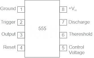
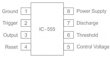
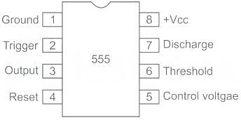
Pin diagram of 555 timer IC

Pin 1 - Ground 
This pin is connected to the ground of the circuit 

Pin 2 - Trigger
The trigger pin is used to feed the trigger input to the 555 IC is set up as a monostable multivibrator. This pin is an inverting input of a comparator and is responsible for the transition of flip-flops from set to reset. The output of the timer depends on the amplitude of the external trigger pulse applied to this pin.

Pin 3 - Output
The output of the timer is present at pin 3. load can be connected at the output. 

​Pin 4 - Reset pin
Whenever the timer IC is to be reset, a negative pulse (low voltage) is applied to reset the pin, the output is reset (Zero) irrespective of the input condition. (Option 1 is correct).

Pin 5 - Control voltage 
This pin provides access to the internal voltage divider (2/3 Vcc by default) By applying a voltage to this pin the timing characteristics can be changed.

Pin 6 - Threshold
when the voltage at this pin is greater than the voltage at CONTROL (2⁄3 VCC except when CONTROL is driven by an external signal), then the OUTPUT high state timing interval ends, causing the OUTPUT to go to the low state.

Pin 7 - Discharge
This pin can be used to discharge the capacitor between intervals, in phase with the output.

Pin 8 - Vcc
The positive supply voltage is usually between 3 and 15 depending on the variation.

Test: 555 Timer - Question 2

The 555 timer can be used in which of the following configurations?

Detailed Solution for Test: 555 Timer - Question 2

555 timer has 2 modes 

1. Monostable multivibrator
The applications of monostable multivibrator include:

  • Pulse width Modulator
  • Linear Ramp generator
  • frequency divider
  • pulse stretcher
     

2. Astable multivibrator

  • Square Wave Generator
  • voltage-controlled oscillator
  • FSK generator
  • free running oscillator
Test: 555 Timer - Question 3

Consider the following statements regarding 555 timer:
1. It operates on -5 V to +18 V supply voltage in both free running and one-shot modes.
2. It has a high current output and it can source or sink 500 mA.
3. The output can drive TTL and has a temperature stability of 80 parts per million (ppm) per degree celsius change in temperature or equivalently 0.008 %/°C.
Which of the above statements are not correct?

Detailed Solution for Test: 555 Timer - Question 3

555 Timer IC:

  • The 555 timer chip is extremely robust and stable 8-pin device.
  • It can be operated either as a very accurate Monostable, Bistable or Astable Multivibrator to produce a variety of applications such as one-shot or delay timers, pulse generation, LED and lamp flashers, alarms and tone generation, logic clocks, frequency division, power supplies and converters etc.

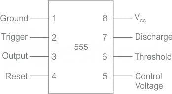
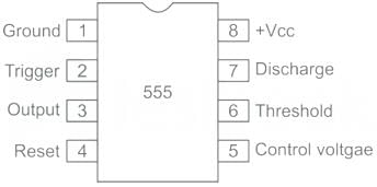
Pin Diagram:

Characteristics of 555 timer IC:

  • Typical operating voltage is +5V, can withstand a maximum of +18V.
  • The source/sink current of the output pin is 200mA.
  • Consumes up to 3mA when operating at +5V.
  • Trigger Voltage is 1.67 when operating at +5V.
  • Operating Temperature is 70 degree Celsius.
  • Available in 8-pin PDIP, SOIC, and VSSOP packages.
Test: 555 Timer - Question 4

For trigger voltage less than 1/3 Vcc, the output of IC 555 is:

Detailed Solution for Test: 555 Timer - Question 4
  • A low voltage (less than 1/3 the supply voltage) applied for short time to the trigger input that cause output go high.
  • The output will remain high until a high voltage is applied to the threshold input.
  • In output low state the voltage will be close to 0 V. 
Test: 555 Timer - Question 5

In a multivibrator, both the output states are quasi stable. The output varies from state to state and the circuit acts like a free running square wave oscillator. The type of multivibrator is

Detailed Solution for Test: 555 Timer - Question 5

Astable Multivibrator:

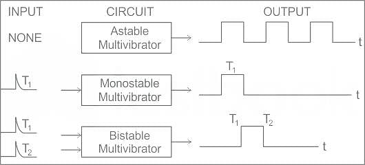
  • An Astable multivibrator is such a circuit that it automatically switches between the two states continuously without the application of any external pulse for its operation, i.e. it is unstable in any state.
  • As this produces a continuous square wave output, it is called a free-running multivibrator.

A Monostable multivibrator has a stable state and a quasi-stable state. This has a trigger input to one transistor. So, one transistor changes its state automatically, while the other one needs a trigger input to change its state.
A Bistable multivibrator has both the two states stable. It requires two trigger pulses to be applied to change the states. Until the trigger input is given, this multivibrator cannot change its state.

Test: 555 Timer - Question 6

Which of the following are the basic elements in a 555 timer IC?
(a) Two comparators
(b) A flip-flop
(c) A discharge transistor
(d) A resistive voltage divider

Detailed Solution for Test: 555 Timer - Question 6

The 555 timer is one of the most popular IC used in timing circuits.
It is an integrated circuit used in a variety of timer, pulse generation, and oscillator applications.
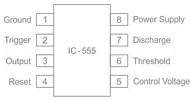
The Pin configuration of IC-555 is as shown:

  • Pin 5 of 555 Timer is the control pin. 
  • This makes the oscillator cycle more consistent.
  • This pin can also be used to change the internal voltage reference to allow modifying the oscillator frequency or duty cycle.
  • The single 555 Timer chip in its basic form is a Bipolar 8-pin mini DIP device.
  • It consists of 25 transistors, 2 diodes, 16 registers to form two comparators, a flip-flop, and high current output.
  • Pin 7 is called a Discharge pin which is connected directly to the collector of an internal NPN transistor which is used to “discharge” the timing capacitor to the ground when the output at pin 3 switches low.
  • The 555 Timer’s name is derived as there are three 5 kΩ resistors connected internally producing a voltage divider network between the supply voltage at pin 8 and ground at pin 1.
Test: 555 Timer - Question 7

What is the most popular IC used in timing circuits?

Detailed Solution for Test: 555 Timer - Question 7

555 timer is one of the most popular IC used in timing circuits.
It is an integrated circuit used in a variety of timer, pulse generation, and oscillator applications.
The Pin configuration of IC-555 is as shown:

  • Pin 5 of 555 Timer is the control pin. 
  • This makes the oscillator cycle more consistent.
  • This pin can also be used to change the internal voltage reference to allow modifying the oscillator frequency or duty cycle.

It has three operating modes:

  • Astable Mode: In this mode, the 555 IC can be used as an oscillator, pulse generator, logic clocks, etc.
  • Monostable mode: In this mode, the 555 functions as a ‘one-shot’ pulse generator and finds use in frequency divider, timers, pulse detection, touch switches.
  • Bistable mode: In this mode, the 555 IC can be operated as a flip-flop, latches.
Test: 555 Timer - Question 8

The control terminal (pin5) of 555 timer IC is normally connected to ground through a capacitor (∼ 0.01μF). This is to

Detailed Solution for Test: 555 Timer - Question 8

Control pin of 555 Timer:
The control pin on the 555 timers is normally connected to the ground through a capacitor (∼ 0.01μF because the noise from the supply line can ride through this simple divider adding small capacitor filters out high-frequency noise that can cause the comparison point to vary slightly

  • Pin 5 of 555 Timer is the control pin. 
  • This makes the oscillator cycle more consistent.
  • This pin can also be used to change the internal voltage reference to allow modifying the oscillator frequency or duty cycle.

IC 555 has three operating modes namely:

  • Bistable mode or Schmitt Trigger
  • Monostable Mode: In this mode, the 555 functions as a pulse generator.
  • Astable(Free running) Mode: In this mode, the 555 operates as an oscillator.
Test: 555 Timer - Question 9

A multivibrator is a circuit which generates

Detailed Solution for Test: 555 Timer - Question 9

A multivibrator using a 555 timer:
An astable multivibrator is also called a Square wave generator or Free running oscillator.

It generates a square wave output.
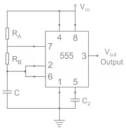
The schematic diagram of the Astable multivibrator using a 555 timer is shown below.

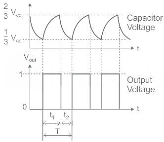
The output waveform:

Hence, The output waveform of a multivibrator is a Square wave.

Test: 555 Timer - Question 10

The most popular IC used in timing circuit is

Detailed Solution for Test: 555 Timer - Question 10

555 timer:
The 555 timer IC is an integrated circuit used in a variety of timer, pulse generation, and oscillator applications.

It has three operating modes

  • Astable mode: In this mode, the 555 IC can be used as an oscillator, pulse generator, logic clocks, etc.
  • Monostable mode: In this mode, the 555 functions as a ‘one-shot’ pulse generator and finds uses in frequency divider, timers, pulse detection, touch switches.
  • Bistable mode: In this mode, the 555 IC can be operated as a flip-flop, latches.555 timer IC with the
    of pins is shown below:
25 docs|263 tests
Information about Test: 555 Timer Page
In this test you can find the Exam questions for Test: 555 Timer solved & explained in the simplest way possible. Besides giving Questions and answers for Test: 555 Timer, EduRev gives you an ample number of Online tests for practice
Download as PDF