Test: SFD & BMD Level - 3 - Mechanical Engineering MCQ
20 Questions MCQ Test Strength of Materials (SOM) - Test: SFD & BMD Level - 3
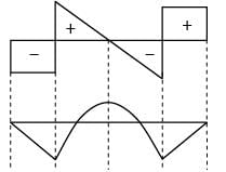
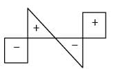
The shear force diagram is shown above for a loaded beam. The corresponding bending moment diagram is represented by

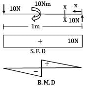
Consider the following statements for a simply supported beam subjected to a couple of 10 kN-m at its mid-span.
1. Bending moment is zero at the ends and maximum at the center
2. Bending moment is constant over the entire length of the beam
3. Shear force is constant over the entire length of the beam
4. Shear force is zero over the entire length of the beam Which of the statements given above are correct?
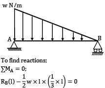
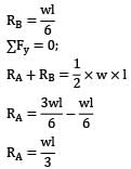
A simply supported beam of span ‘l’ subjected to a load linearly varying from zero at one end to w/m at the other, develops a maximum shear force of
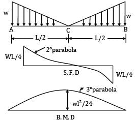
The left half of a simply supported beam of span “L” is loaded with u. d. l of w/meter run. The point of maximum B.M will occur at
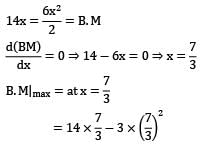
For the loaded beam as shown in the figure max B.M occurs at

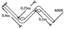
A load perpendicular to the plane of the handle is applied at the free end as shown in the given figure. The values of shear forces (S.F.), Bending Moment (B.M.) and torque at the fixed end of the handle have been determined respectively as 400N, 340Nm and 100 by a student. Among these values, those of
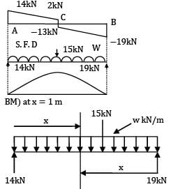
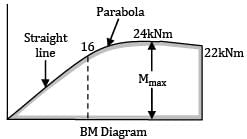
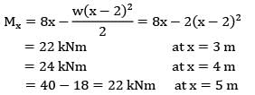
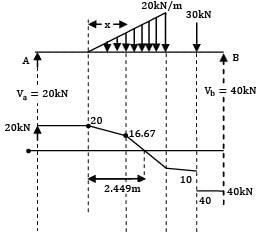
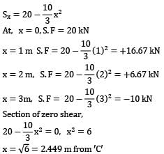
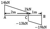
The shear force diagram of a loaded beam is shown in the following figure. The maximum bending moment of the beam is
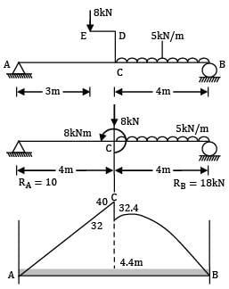
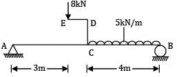
A beam AB, 8 m long hinged at end A and roller supported at end B carries a point load of 8 kN of crank ED = 1 m and uniformly distributed load of 5 kN/m over CB = 4 m. Then the bending moment where SF is zero is __________ kN-m.
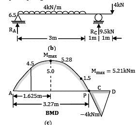
A cantilever ABC, 5 m long is propped by a force of 8 kN at free end as shown in figure (a). It carries a UDL of 4 kN/m over BC = 3 m.
The point of contra-flexure is

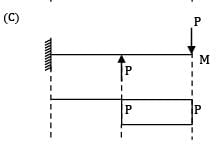
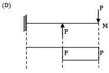
Which one of the given bending moment diagrams correctly represents that of the loaded beam shown in figure?
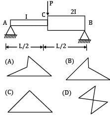
Option~
(A) 
(B) 
(C) 
(D) 
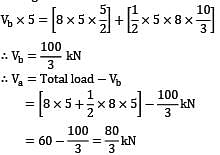
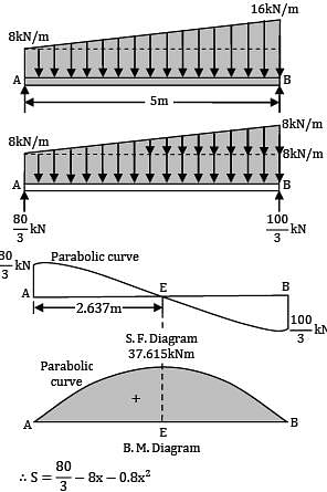
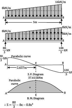
The intensity of loading on a simply supported beam of 5 meters span increases uniformly from 8 kN/m at one end to 16 kN/m at the other end. The magnitude of the maximum bending moment is __________ kN-m.
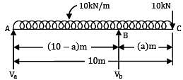
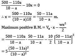
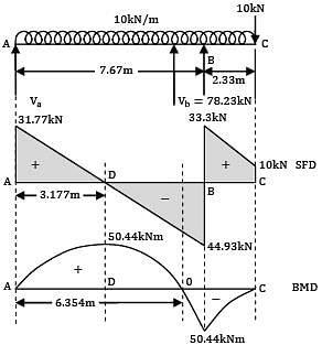
A beam of uniform section 10 metres long carries a uniformly distributed load of 10 kN per metre over the whole length and a concentrated load of 10 kN at the right end. If the beam is freely supported at the left end, then the position of the second support so that maximum bending moment for the beam shall be as small as possible is __________ m.
A horizontal beam is simply supported at the ends and carries a uniformly distributed load of 10 kN/m between the supports placed 10 m apart. Anticlockwise moments of 150 kNm and 100 kNm are applied to the left and right ends of the beam at the supports. The point of contra-flexure from the right hand side support is __________m

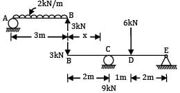
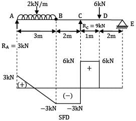
A beam AB, 3 m long is hinged at end B to another beam BCDE, 5 m long as shown in figure (a). Beam AB carries a UDL of 2 kN/m over its full length, while beam BCDE carries a point load of 6 kNm, 1 m from C at D. The maximum shear force in the beam is __________

Consider the following loading condition
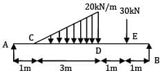
Find maximum shear force.
For the shown loading case the maximum bending moment will be __________

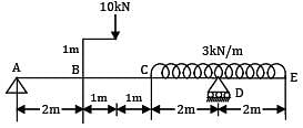
For the beam ABCDE shown in figure, the maximum bending moment is __________ kN-m.
SF diagram of a beam ABCD 6 m long, hinged at A and roller supported at C, is shown in figure. The distance of the point of contra-flexure from the left support is __________.

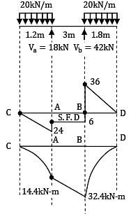
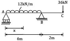
A beam ABC of segmental length AB=6m and BC = 2 m carries uniformly distributed load of intensity 12kN/m on AB and a point load of 36kN at C. Assuming simple supports at A and B, the point of contra flexure can be located at a section ___________m to the right of support A.
|
37 videos|41 docs|47 tests
|


