Case Based Questions Test: Ray Optics & Optical Instruments - 2 - NEET MCQ
15 Questions MCQ Test Topic-wise MCQ Tests for NEET - Case Based Questions Test: Ray Optics & Optical Instruments - 2
Read the following text and answer the following questions on the basis of the same:
Negative Refractive Index: One of the most fundamental phenomena in optics is refraction. When a beam of light crosses the interface between two different materials, its path is altered depending on the difference in the refractive indices of the materials. The greater the difference, the greater the refraction of the beam. For all known naturally occurring materials the refractive index assumes only positive values. But does this have to be the case?
In 1967, Soviet physicist Victor Veselago hypothesized that a material with a negative refractive index could exist without violating any of the laws of physics.
Veselago predicted that this remarkable material would exhibit a wide variety of new optical phenomena. However, until recently no one had found such a material and Veselago’s ideas had remained untested. Recently, meta-material samples are being tested for negative refractive index. But the experiments show significant losses and this could be an intrinsic property of negativeindex materials.
Snell’s law is satisfied for the materials having a negative refractive index, but the direction of the refracted light ray is ‘mirror-imaged’ about the normal to the surface.
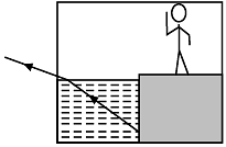
There will be an interesting difference in image formation if a vessel is filled with “negative water” having refractive index – 1.33 instead of regular water having refractive index 1.33.
Say, there is a fish in a vessel filled with negative water. The position of the fish is such that the observer cannot see it due to normal refraction since the refracted ray does not reach to his eye.

But due to negative refraction, he will be able to see it since the refracted ray now reaches his eye.
Q. Is Snell’s law applicable for negative refraction ?


Read the following text and answer the following questions on the basis of the same:
Negative Refractive Index: One of the most fundamental phenomena in optics is refraction. When a beam of light crosses the interface between two different materials, its path is altered depending on the difference in the refractive indices of the materials. The greater the difference, the greater the refraction of the beam. For all known naturally occurring materials the refractive index assumes only positive values. But does this have to be the case?
In 1967, Soviet physicist Victor Veselago hypothesized that a material with a negative refractive index could exist without violating any of the laws of physics.
Veselago predicted that this remarkable material would exhibit a wide variety of new optical phenomena. However, until recently no one had found such a material and Veselago’s ideas had remained untested. Recently, meta-material samples are being tested for negative refractive index. But the experiments show significant losses and this could be an intrinsic property of negativeindex materials.
Snell’s law is satisfied for the materials having a negative refractive index, but the direction of the refracted light ray is ‘mirror-imaged’ about the normal to the surface.
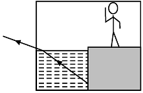
There will be an interesting difference in image formation if a vessel is filled with “negative water” having refractive index – 1.33 instead of regular water having refractive index 1.33.
Say, there is a fish in a vessel filled with negative water. The position of the fish is such that the observer cannot see it due to normal refraction since the refracted ray does not reach to his eye.
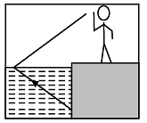
But due to negative refraction, he will be able to see it since the refracted ray now reaches his eye.
Q. When the angle of incidence will be equal to angle of refraction for material having negative refraction index?


| 1 Crore+ students have signed up on EduRev. Have you? Download the App |
Read the following text and answer the following questions on the basis of the same:
Negative Refractive Index: One of the most fundamental phenomena in optics is refraction. When a beam of light crosses the interface between two different materials, its path is altered depending on the difference in the refractive indices of the materials. The greater the difference, the greater the refraction of the beam. For all known naturally occurring materials the refractive index assumes only positive values. But does this have to be the case?
In 1967, Soviet physicist Victor Veselago hypothesized that a material with a negative refractive index could exist without violating any of the laws of physics.
Veselago predicted that this remarkable material would exhibit a wide variety of new optical phenomena. However, until recently no one had found such a material and Veselago’s ideas had remained untested. Recently, meta-material samples are being tested for negative refractive index. But the experiments show significant losses and this could be an intrinsic property of negativeindex materials.
Snell’s law is satisfied for the materials having a negative refractive index, but the direction of the refracted light ray is ‘mirror-imaged’ about the normal to the surface.
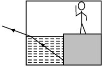
There will be an interesting difference in image formation if a vessel is filled with “negative water” having refractive index – 1.33 instead of regular water having refractive index 1.33.
Say, there is a fish in a vessel filled with negative water. The position of the fish is such that the observer cannot see it due to normal refraction since the refracted ray does not reach to his eye.
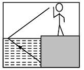
But due to negative refraction, he will be able to see it since the refracted ray now reaches his eye.
Q. Who hypothesized that a material may have a negative refractive index ?


Read the following text and answer the following questions on the basis of the same:
Negative Refractive Index: One of the most fundamental phenomena in optics is refraction. When a beam of light crosses the interface between two different materials, its path is altered depending on the difference in the refractive indices of the materials. The greater the difference, the greater the refraction of the beam. For all known naturally occurring materials the refractive index assumes only positive values. But does this have to be the case?
In 1967, Soviet physicist Victor Veselago hypothesized that a material with a negative refractive index could exist without violating any of the laws of physics.
Veselago predicted that this remarkable material would exhibit a wide variety of new optical phenomena. However, until recently no one had found such a material and Veselago’s ideas had remained untested. Recently, meta-material samples are being tested for negative refractive index. But the experiments show significant losses and this could be an intrinsic property of negativeindex materials.
Snell’s law is satisfied for the materials having a negative refractive index, but the direction of the refracted light ray is ‘mirror-imaged’ about the normal to the surface.

There will be an interesting difference in image formation if a vessel is filled with “negative water” having refractive index – 1.33 instead of regular water having refractive index 1.33.
Say, there is a fish in a vessel filled with negative water. The position of the fish is such that the observer cannot see it due to normal refraction since the refracted ray does not reach to his eye.
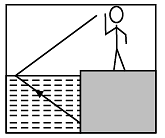
But due to negative refraction, he will be able to see it since the refracted ray now reaches his eye.
Q. A ray incident on normal glass and “negative glass” at an angle 60°. If the magnitude of angle of refraction in normal glass is 45° then, what will be the magnitude of angle of refraction in the “negative glass”?
Read the following text and answer the following questions on the basis of the same:
Negative Refractive Index: One of the most fundamental phenomena in optics is refraction. When a beam of light crosses the interface between two different materials, its path is altered depending on the difference in the refractive indices of the materials. The greater the difference, the greater the refraction of the beam. For all known naturally occurring materials the refractive index assumes only positive values. But does this have to be the case?
In 1967, Soviet physicist Victor Veselago hypothesized that a material with a negative refractive index could exist without violating any of the laws of physics.
Veselago predicted that this remarkable material would exhibit a wide variety of new optical phenomena. However, until recently no one had found such a material and Veselago’s ideas had remained untested. Recently, meta-material samples are being tested for negative refractive index. But the experiments show significant losses and this could be an intrinsic property of negativeindex materials.
Snell’s law is satisfied for the materials having a negative refractive index, but the direction of the refracted light ray is ‘mirror-imaged’ about the normal to the surface.

There will be an interesting difference in image formation if a vessel is filled with “negative water” having refractive index – 1.33 instead of regular water having refractive index 1.33.
Say, there is a fish in a vessel filled with negative water. The position of the fish is such that the observer cannot see it due to normal refraction since the refracted ray does not reach to his eye.

But due to negative refraction, he will be able to see it since the refracted ray now reaches his eye.
Q. Which of the following is the intrinsic property of negative-index materials?
Read the following text and answer the following questions on the basis of the same:
First Surface Mirror:
Normally we use back surface mirrors. These are considered low precision mirrors because they actually have two reflecting surfaces. The first reflecting surface is the initial surface on the pane of glass where a small percentage of light is reflected off the surface. The second reflecting surface is the aluminium coating where a high percentage of light is reflected off the surface.
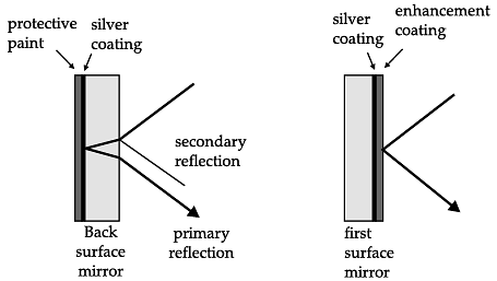
This dual reflection effect of a low precision mirror causes a loss of contrast and image distortion that is undesirable in high precision applications like rear projection systems, scanners and reflecting telescopes. In these cases good image quality is highly preferred, and this is where a front surface mirror is desired for clarity and single image reflection. First surface mirrors are quite common in professional optics. However, compared with back surface mirrors, they have the important disadvantage of being substantially more sensitive. The front surface may be touched, and a metal coating on the front surface is substantially more sensitive than a bare glass surface. For example, fingerprints can easily cause oxidation of the metal.. Also, moisture or aggressive gases may cause oxidation of the mirror coating.
Q. Light incident on back surface mirror suffers:
Read the following text and answer the following questions on the basis of the same:
First Surface Mirror:
Normally we use back surface mirrors. These are considered low precision mirrors because they actually have two reflecting surfaces. The first reflecting surface is the initial surface on the pane of glass where a small percentage of light is reflected off the surface. The second reflecting surface is the aluminium coating where a high percentage of light is reflected off the surface.
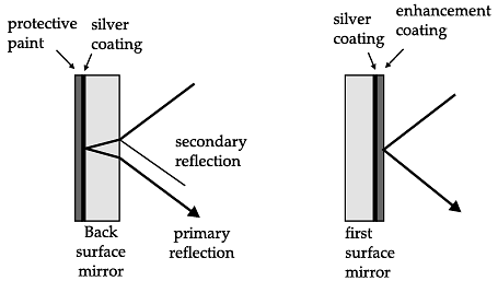
This dual reflection effect of a low precision mirror causes a loss of contrast and image distortion that is undesirable in high precision applications like rear projection systems, scanners and reflecting telescopes. In these cases good image quality is highly preferred, and this is where a front surface mirror is desired for clarity and single image reflection. First surface mirrors are quite common in professional optics. However, compared with back surface mirrors, they have the important disadvantage of being substantially more sensitive. The front surface may be touched, and a metal coating on the front surface is substantially more sensitive than a bare glass surface. For example, fingerprints can easily cause oxidation of the metal.. Also, moisture or aggressive gases may cause oxidation of the mirror coating.
Q. Image formed of front coated mirror:
Read the following text and answer the following questions on the basis of the same:
First Surface Mirror:
Normally we use back surface mirrors. These are considered low precision mirrors because they actually have two reflecting surfaces. The first reflecting surface is the initial surface on the pane of glass where a small percentage of light is reflected off the surface. The second reflecting surface is the aluminium coating where a high percentage of light is reflected off the surface.

This dual reflection effect of a low precision mirror causes a loss of contrast and image distortion that is undesirable in high precision applications like rear projection systems, scanners and reflecting telescopes. In these cases good image quality is highly preferred, and this is where a front surface mirror is desired for clarity and single image reflection. First surface mirrors are quite common in professional optics. However, compared with back surface mirrors, they have the important disadvantage of being substantially more sensitive. The front surface may be touched, and a metal coating on the front surface is substantially more sensitive than a bare glass surface. For example, fingerprints can easily cause oxidation of the metal.. Also, moisture or aggressive gases may cause oxidation of the mirror coating.
Q. Precision of back surface mirrors is:
Read the following text and answer the following questions on the basis of the same:
First Surface Mirror:
Normally we use back surface mirrors. These are considered low precision mirrors because they actually have two reflecting surfaces. The first reflecting surface is the initial surface on the pane of glass where a small percentage of light is reflected off the surface. The second reflecting surface is the aluminium coating where a high percentage of light is reflected off the surface.
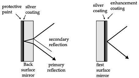
This dual reflection effect of a low precision mirror causes a loss of contrast and image distortion that is undesirable in high precision applications like rear projection systems, scanners and reflecting telescopes. In these cases good image quality is highly preferred, and this is where a front surface mirror is desired for clarity and single image reflection. First surface mirrors are quite common in professional optics. However, compared with back surface mirrors, they have the important disadvantage of being substantially more sensitive. The front surface may be touched, and a metal coating on the front surface is substantially more sensitive than a bare glass surface. For example, fingerprints can easily cause oxidation of the metal.. Also, moisture or aggressive gases may cause oxidation of the mirror coating.
Q. In professional optics:
Read the following text and answer the following questions on the basis of the same:
First Surface Mirror:
Normally we use back surface mirrors. These are considered low precision mirrors because they actually have two reflecting surfaces. The first reflecting surface is the initial surface on the pane of glass where a small percentage of light is reflected off the surface. The second reflecting surface is the aluminium coating where a high percentage of light is reflected off the surface.
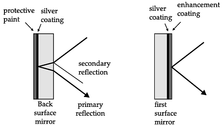
This dual reflection effect of a low precision mirror causes a loss of contrast and image distortion that is undesirable in high precision applications like rear projection systems, scanners and reflecting telescopes. In these cases good image quality is highly preferred, and this is where a front surface mirror is desired for clarity and single image reflection. First surface mirrors are quite common in professional optics. However, compared with back surface mirrors, they have the important disadvantage of being substantially more sensitive. The front surface may be touched, and a metal coating on the front surface is substantially more sensitive than a bare glass surface. For example, fingerprints can easily cause oxidation of the metal.. Also, moisture or aggressive gases may cause oxidation of the mirror coating.
Q. The front surface coating:
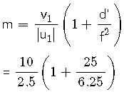
A compound microscope is an optical instrument used for observing highly magnified images of tiny objects. Magnifying power of a compound microscope is defined as the ratio of the angle subtended at the eye by the final image to the angle subtended at the eye by the object, when both the final image and the objects are situated at the least distance of distinct vision from the eye. It can be given that: m=me x mo, where me is the magnification produced by the eye lens and mo is the magnification produced by the objective lens.
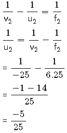
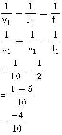
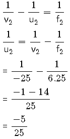
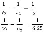
Consider a compound microscope that consists of an objective lens of focal length 2.0 cm and an eyepiece of focal length 6.25 cm separated by a distance of 15 cm.
Q. How far from the objective should an object be placed in order to obtain the condition described in part (i)?
A compound microscope is an optical instrument used for observing highly magnified images of tiny objects. Magnifying power of a compound microscope is defined as the ratio of the angle subtended at the eye by the final image to the angle subtended at the eye by the object, when both the final image and the objects are situated at the least distance of distinct vision from the eye. It can be given that: m=me x mo, where me is the magnification produced by the eye lens and mo is the magnification produced by the objective lens.
Consider a compound microscope that consists of an objective lens of focal length 2.0 cm and an eyepiece of focal length 6.25 cm separated by a distance of 15 cm.
Q. The intermediate image formed by the objective of a compound microscope is
A compound microscope is an optical instrument used for observing highly magnified images of tiny objects. Magnifying power of a compound microscope is defined as the ratio of the angle subtended at the eye by the final image to the angle subtended at the eye by the object, when both the final image and the objects are situated at the least distance of distinct vision from the eye. It can be given that: m=me x mo, where me is the magnification produced by the eye lens and mo is the magnification produced by the objective lens.
Consider a compound microscope that consists of an objective lens of focal length 2.0 cm and an eyepiece of focal length 6.25 cm separated by a distance of 15 cm.
Q. The object distance for eye-piece, so that final image is formed at the least distance of distinct vision, will be
A compound microscope is an optical instrument used for observing highly magnified images of tiny objects. Magnifying power of a compound microscope is defined as the ratio of the angle subtended at the eye by the final image to the angle subtended at the eye by the object, when both the final image and the objects are situated at the least distance of distinct vision from the eye. It can be given that: m=me x mo, where me is the magnification produced by the eye lens and mo is the magnification produced by the objective lens.
Consider a compound microscope that consists of an objective lens of focal length 2.0 cm and an eyepiece of focal length 6.25 cm separated by a distance of 15 cm.
Q. What is the magnifying power of the microscope in case of least distinct vision?
A compound microscope is an optical instrument used for observing highly magnified images of tiny objects. Magnifying power of a compound microscope is defined as the ratio of the angle subtended at the eye by the final image to the angle subtended at the eye by the object, when both the final image and the objects are situated at the least distance of distinct vision from the eye. It can be given that: m=me x mo, where me is the magnification produced by the eye lens and mo is the magnification produced by the objective lens.
Consider a compound microscope that consists of an objective lens of focal length 2.0 cm and an eyepiece of focal length 6.25 cm separated by a distance of 15 cm.
Q. The magnifying power of a compound microscope increases with
|
9 docs|1272 tests
|


