Electrical Engineering (EE) Exam  >  Electrical Engineering (EE) Tests  >  GATE Electrical Engineering (EE) Mock Test Series 2025  >  Test: Balanced Three Phase Circuits - Electrical Engineering (EE) MCQ

Test: Balanced Three Phase Circuits - Electrical Engineering (EE) MCQ


Test Description

10 Questions MCQ Test GATE Electrical Engineering (EE) Mock Test Series 2025 - Test: Balanced Three Phase Circuits

Test: Balanced Three Phase Circuits for Electrical Engineering (EE) 2025 is part of GATE Electrical Engineering (EE) Mock Test Series 2025 preparation. The Test: Balanced Three Phase Circuits questions and answers have been prepared according to the Electrical Engineering (EE) exam syllabus.The Test: Balanced Three Phase Circuits MCQs are made for Electrical Engineering (EE) 2025 Exam. Find important definitions, questions, notes, meanings, examples, exercises, MCQs and online tests for Test: Balanced Three Phase Circuits below.
Solutions of Test: Balanced Three Phase Circuits questions in English are available as part of our GATE Electrical Engineering (EE) Mock Test Series 2025 for Electrical Engineering (EE) & Test: Balanced Three Phase Circuits solutions in Hindi for GATE Electrical Engineering (EE) Mock Test Series 2025 course. Download more important topics, notes, lectures and mock test series for Electrical Engineering (EE) Exam by signing up for free. Attempt Test: Balanced Three Phase Circuits | 10 questions in 30 minutes | Mock test for Electrical Engineering (EE) preparation | Free important questions MCQ to study GATE Electrical Engineering (EE) Mock Test Series 2025 for Electrical Engineering (EE) Exam | Download free PDF with solutions
Test: Balanced Three Phase Circuits - Question 1

In a balanced three-phase system-delta load, if we assume the line voltage is VRY = V∠0⁰ as a reference phasor. Then the source voltage VYB is?

Detailed Solution for Test: Balanced Three Phase Circuits - Question 1

As the line voltage VRY = V∠0⁰ is taken as a reference phasor. Then the source voltage VYB is V∠-120⁰.

Test: Balanced Three Phase Circuits - Question 2

 In a delta-connected load, the relation between line voltage and the phase voltage is?

Detailed Solution for Test: Balanced Three Phase Circuits - Question 2

In a delta-connected load, the relation between line voltage and the phase voltage is line voltage = phase voltage.

Test: Balanced Three Phase Circuits - Question 3

If the load impedance is Z∠Ø, the expression obtained for current (IY) is?

Detailed Solution for Test: Balanced Three Phase Circuits - Question 3

As the load impedance is Z∠Ø, the current flows in the three load impedances and the current flowing in the Y impedance is IY = VYB∠120⁰/Z∠Ø = (V/Z)∠-120-Ø.

Test: Balanced Three Phase Circuits - Question 4

A three-phase balanced delta connected load of (4 + j8) Ω is connected across a 400V, 3 – Ø balanced supply. Determine the phase current IR. Assume the phase sequence to be RYB.

Detailed Solution for Test: Balanced Three Phase Circuits - Question 4

Taking the line voltage VRY = V∠0⁰ as a reference VRY = 400∠0⁰V, VYB = 400 ∠ -120 ⁰V and VBR = 400∠-240⁰V. Impedance per phase = (4 + j8) Ω = 8.94∠63.4⁰Ω. Phase current IR = (400∠0o)/(8.94∠63.4o )= 44.74 ∠ -63.4⁰A.

Test: Balanced Three Phase Circuits - Question 5

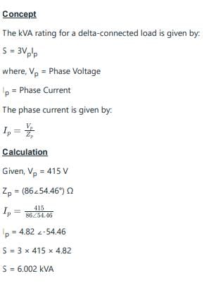
A 415 V, three-phase star-connected alternator supplies a delta-connected load, each phase of which has an impedance of (86∠54.46°) Ω. Calculate kVA rating of the alternator, neglecting losses in the line between the alternator and load.


Detailed Solution for Test: Balanced Three Phase Circuits - Question 5

Test: Balanced Three Phase Circuits - Question 6

In a balanced three-phase system-delta load, if we assume the line voltage is VRY = V∠0⁰ as a reference phasor. Then the source voltage VBR is?

Detailed Solution for Test: Balanced Three Phase Circuits - Question 6

As the line voltage VRY = V∠0⁰ is taken as a reference phasor. Then the source voltage VBR is V∠-240⁰.

Test: Balanced Three Phase Circuits - Question 7

If the load impedance is Z∠Ø, the current (IR) is?

Detailed Solution for Test: Balanced Three Phase Circuits - Question 7

As the load impedance is Z∠Ø, the current flows in the three load impedances and the current flowing in the R impedance is IR = VBR∠0⁰/Z∠Ø = (V/Z)∠-Ø.

Test: Balanced Three Phase Circuits - Question 8

In wye or star connection _____________ of the three phases are joined together within the alternator.

Detailed Solution for Test: Balanced Three Phase Circuits - Question 8

In wye or star connection, similar ends of the three phases are joined together within the alternator. The common terminal so formed is referred to as the neutral point or neutral terminal.

Test: Balanced Three Phase Circuits - Question 9

The voltage between ______________ is called line voltage.

Detailed Solution for Test: Balanced Three Phase Circuits - Question 9

The voltage between line and line is called line voltage. And the voltage between line and neutral point is called phase voltage. The currents flowing through the phases are called the phase currents, while those flowing in the lines are called the line currents.

Test: Balanced Three Phase Circuits - Question 10

There are three voltage sources. Voltage Source 1 gives 200V peak voltage; voltage Source 2 gives 100V peak which lags behind voltage Source 1 by 120 deg; and voltage Source 3 gives 100V peak which leads voltage Source 1 by 120 deg. If these voltage sources and a 1Ω resister are connected in series, what is the power dissipation in the resistor?

Detailed Solution for Test: Balanced Three Phase Circuits - Question 10

Concept:
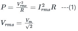
Power dissipation by resistor is given as:

Where,

Vrms = RMS value of voltage

Irms = RMS value of current

R = Resistance

Vm = Peak or maximum value of voltage

Calculation:

Given-

R = 1 Ω, V1 = 200∠0°, V2 = 100∠120°, V3 = 100∠-120°  

All three voltage sources are connected in series, therefore equivalent voltage is

V = V+ V2 + V3 = 200∠0° + 100∠120° + 100∠-120°  

V = 200(cos0° + j sin0°) + 100(cos120° + j sin120°) + 100[cos(-120°) + j sin(-120°)]

V = 100∠0° Volts

Since, R = 1 Ω:

∴ Vrms = Irms
The power dissipation in the resistor will be:

P = 5000 W

25 docs|247 tests
Information about Test: Balanced Three Phase Circuits Page
In this test you can find the Exam questions for Test: Balanced Three Phase Circuits solved & explained in the simplest way possible. Besides giving Questions and answers for Test: Balanced Three Phase Circuits, EduRev gives you an ample number of Online tests for practice
Download as PDF