Electrical Engineering (EE) Exam  >  Electrical Engineering (EE) Tests  >  GATE Electrical Engineering (EE) Mock Test Series 2025  >  Test: Sequential Logic Circuits- 2 - Electrical Engineering (EE) MCQ

Test: Sequential Logic Circuits- 2 - Electrical Engineering (EE) MCQ


Test Description

15 Questions MCQ Test GATE Electrical Engineering (EE) Mock Test Series 2025 - Test: Sequential Logic Circuits- 2

Test: Sequential Logic Circuits- 2 for Electrical Engineering (EE) 2025 is part of GATE Electrical Engineering (EE) Mock Test Series 2025 preparation. The Test: Sequential Logic Circuits- 2 questions and answers have been prepared according to the Electrical Engineering (EE) exam syllabus.The Test: Sequential Logic Circuits- 2 MCQs are made for Electrical Engineering (EE) 2025 Exam. Find important definitions, questions, notes, meanings, examples, exercises, MCQs and online tests for Test: Sequential Logic Circuits- 2 below.
Solutions of Test: Sequential Logic Circuits- 2 questions in English are available as part of our GATE Electrical Engineering (EE) Mock Test Series 2025 for Electrical Engineering (EE) & Test: Sequential Logic Circuits- 2 solutions in Hindi for GATE Electrical Engineering (EE) Mock Test Series 2025 course. Download more important topics, notes, lectures and mock test series for Electrical Engineering (EE) Exam by signing up for free. Attempt Test: Sequential Logic Circuits- 2 | 15 questions in 45 minutes | Mock test for Electrical Engineering (EE) preparation | Free important questions MCQ to study GATE Electrical Engineering (EE) Mock Test Series 2025 for Electrical Engineering (EE) Exam | Download free PDF with solutions
Test: Sequential Logic Circuits- 2 - Question 1

Assertion (A): The indeterminate condition of the J-K flip-flop is permitted in S-R flip-flop.
Reason (R): A J-Kfiip-flop has a characteristic similar to that of an S-R flip-flop.

Detailed Solution for Test: Sequential Logic Circuits- 2 - Question 1

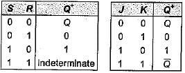
The truth table for S-ffand J-Kflip-flop are shown below.

It is clear from the above truth table that when S = R = 1, the output of S-R flip-flop is indeterminate. However, when J = K = 1, the output of J-Kflip-flop is (not indeterminate). Therefore, the indeterminate condition of the S-R flip-flop is permitted in a J-Kflip-flop.
A J-Kflip-flop has a characteristic similar to that of an S-R flip-flop which is evident from the above truth tables.
Hence, assertion is false but reason is true.

Test: Sequential Logic Circuits- 2 - Question 2

The J-K master-slave flip-flops in figure shown below has its J and K inputs tied to + VCC and a series of pulses is applied to its CLK input.

The waveform at G is given by

Detailed Solution for Test: Sequential Logic Circuits- 2 - Question 2

Let the flip-flop is initially reset.
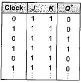
The truth table for aiven circuit is shown below

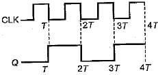
Thus, the waveform for Q will be as shown below

Test: Sequential Logic Circuits- 2 - Question 3

For the J-Kflip-flop shown below to function as a divide-by-2 element, the J and K inputs should be equal to

Detailed Solution for Test: Sequential Logic Circuits- 2 - Question 3

If J = K = 1, then the truth table will be as show below (Initially flip-flop is.reset).

Thus, the given J-Kflip-flop will work as a divide- by-2 elemen

Test: Sequential Logic Circuits- 2 - Question 4

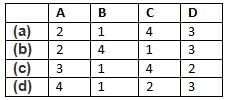
Match List-l with List-II and select the correct answer using the codes given below the lists:
List-I
A. J-K flip-flop
B. D flip-flop
C. Master-slave flip-flop
D. T flip-flop
List-lI
1. Transparent latch
2. Most versatile and widely used of all the flip flops
3. Not widely available as commercial items
4. Pulse triggered flip-flop
Codes:
Detailed Solution for Test: Sequential Logic Circuits- 2 - Question 4

• The J-K flip-flop is the most versatile and most widely used of all the flip-flops.
• Transparent latch is associated with D-flip flop since the clocked D latch is called a transparent D latch, because its output follows the input when the clock is HIGH.
• Master-slave flip-flops are called pulse- triggered flip-flops, because the length of time required for its output to change state equals the width of one (clock) pulse.
• T flip -flop is not widely available as commercial items.

Test: Sequential Logic Circuits- 2 - Question 5

Assertion (A): An unclocked flip-flop is called a latch.​
Reason (R): A latch is constructed using two cross-coupled NAND gates or NOR gates.

Detailed Solution for Test: Sequential Logic Circuits- 2 - Question 5

An unclocked flip-flop is called a latch, because the output of the flip-flop latches on to ‘1’ or ‘0' immediately after the input is applied. Hence, assertion is a correct statement. Reason is also a true statement but not the correct explanation of assertion.

Test: Sequential Logic Circuits- 2 - Question 6

Consider the following statements associated with flip-flops;
1. Any one type of flip-flop can be converted to any other type by providing a suitable combinational circuit.
2. The inputs to a master-slave flip-flop must change when the clock is HIGH.
3. In a master-slave flip-flop, master is level triggered while slave is edge triggered.
4.  Data lock-out flip-flops are nothing but master-slave flip-flops.

Q. Which of the statements given above is/are not correct?

Detailed Solution for Test: Sequential Logic Circuits- 2 - Question 6

• Statement-1 is correct.
• The inputs to a master-slave flip-flops must not change when the clock is HIGH. If they change, the flip-flop gives an output corresponding to the last combination of inputs present before the dock terminals. Hence, statement-2 is not correct.
• In a master-slave flip-flop, master is edge-triggered while slave is level triggered. Thus, statements-3 is not correct.
• Data lock-out flip-flops are nothing but master-slave flip-flops in which the master is an edge triggered flip-flop. Thus, statement-4 is correct.

Test: Sequential Logic Circuits- 2 - Question 7

For the flip-flop shown below, there is one clock pulse for each bit time.
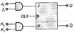
If the following serial data are applied to the flip-flop, then the resulting decimal value of the serial data that appears on the Q output will be (assume that, Q is initially ‘0’)
J1 = 01101101 ; J2 =10011011
K1 = 01101001 ; K2 = 11011011

Detailed Solution for Test: Sequential Logic Circuits- 2 - Question 7

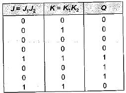
Q = 0 (Initially)

Thus, serial output data at Q
= 00001110 = 14 (Decimal value)

Test: Sequential Logic Circuits- 2 - Question 8

For a flip-flop formed from two NOR gates as shown in figure the unusable state corresponds to
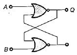
Detailed Solution for Test: Sequential Logic Circuits- 2 - Question 8

Given flip-flop represents S-R latch using NOR gates.
When A = 1, B = 1 we will get invalid or unusable state.

Test: Sequential Logic Circuits- 2 - Question 9

The digital circuit as shown below represents to which one of the following?
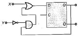
Detailed Solution for Test: Sequential Logic Circuits- 2 - Question 9

Here, 
If X = S and Y = R then, the given circuit circuit represents S-R flip-flop using D flip-flop

Test: Sequential Logic Circuits- 2 - Question 10

If tp is the pulse width, Δt is the propagation delay, T is period of pulse train then which of the following condition can avoid the race around condition?

Detailed Solution for Test: Sequential Logic Circuits- 2 - Question 10

Race around condition occurs in J-K flip-flop when J = K = 1. This condition can be avoided if the propagation delay of flip-flop is more than pulse-width of the clock but less than the clock.
i.e. 2tp < Δt < T

Test: Sequential Logic Circuits- 2 - Question 11

Match List-I (Logic Circuit) with List-ll (Circuit Realization) and select the correct answer using the codes given below the lists:
List-I
A. J-K flip-flop
B. T flip-flop
C. D fiip-flop
List-ll
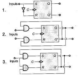
Codes:
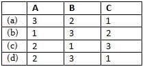
Detailed Solution for Test: Sequential Logic Circuits- 2 - Question 11

For conversion of S-R flip-flop to
A. J-K flip flop:
S = JQ' and R = KQ
B. T Flip-flop:
S = TQ' and = TQ
C. D flip-flop:

Test: Sequential Logic Circuits- 2 - Question 12

The characteristic equation of a T flip-flop is given by

Detailed Solution for Test: Sequential Logic Circuits- 2 - Question 12

For a T flip-flop, Qn+1

Test: Sequential Logic Circuits- 2 - Question 13

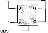
In a J-Kflip-flop we have (shown in figure). Assuming the flip-flop was initially cleared and then clocked for 6-pulses, the sequence at the Q output will be
Detailed Solution for Test: Sequential Logic Circuits- 2 - Question 13

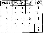
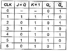
The truth table will be as shown below.

Thus, output Q for 6 clock pulse = 101010.

Test: Sequential Logic Circuits- 2 - Question 14

The output of a J-Kflip-flop Qn is ‘0’. The state of the flip-flop changes when a clock pulse is applied. The possible combination of Jn and Kn inputs could be (‘X' denote don’t care)

Detailed Solution for Test: Sequential Logic Circuits- 2 - Question 14

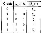
The truth table of J-K flip-flop is shown below.

Given, Qn = 0 initially,
When clock pulse is applied, the state of FF changes to ‘1’ i.e. Qn+ 1 = 1, which is possible,
if, ' J = 1, K = 0 ...(i)
or, Jn = 1 , Kn = ‘X’ ...(ii)
Thus, Jn = 1 and Kn = ‘X (don't care) satisfy the above two conditions.

Test: Sequential Logic Circuits- 2 - Question 15

When a flip-flop is reset, its output will be

Detailed Solution for Test: Sequential Logic Circuits- 2 - Question 15

A FF is set when Q = 1, 
A FF is reset when  Q = 0 ; 

25 docs|247 tests
Information about Test: Sequential Logic Circuits- 2 Page
In this test you can find the Exam questions for Test: Sequential Logic Circuits- 2 solved & explained in the simplest way possible. Besides giving Questions and answers for Test: Sequential Logic Circuits- 2, EduRev gives you an ample number of Online tests for practice
Download as PDF