Analog Electronics - 8 - Free MCQ Test with solutions for GATE EE and Digital
MCQ Practice Test & Solutions: Analog Electronics - 8 (10 Questions)
You can prepare effectively for Electrical Engineering (EE) Analog and Digital Electronics with this dedicated MCQ Practice Test (available with solutions) on the important topic of "Analog Electronics - 8". These 10 questions have been designed by the experts with the latest curriculum of Electrical Engineering (EE) 2026, to help you master the concept.
Test Highlights:
- - Format: Multiple Choice Questions (MCQ)
- - Duration: 30 minutes
- - Number of Questions: 10
Sign up on EduRev for free to attempt this test and track your preparation progress.

Detailed Solution: Question 1

In the above monostable multivibrator circuit above given C = 10 nF. If the frequency of output pulse is 100 kHz the resistor value is _________ kΩ
Detailed Solution: Question 2

Detailed Solution: Question 3
 ≃ 66% > 50%
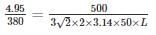
A dc voltage of 380 V with a peak ripple voltage not exceeding 7 V is required to supply a 500 Ω load. Find out the inductance required.
Detailed Solution: Question 4

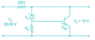
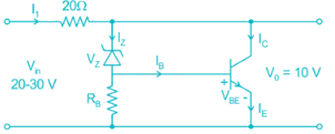
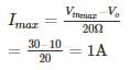
A shunt regular is shown in the figure has a regulated output voltage of 10 V. Given Vz = 9.3, VBE = 0 .7 V, β = 49. Neglecting the current through Resistor RB the ratio of maximum power dissipated in the transistor to the maximum power dissipated in the Zener diode is ________
Detailed Solution: Question 5

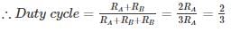
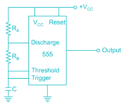
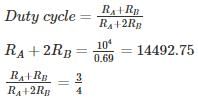
For the circuit shown, the value of C = 1 nF, the value of RA & RB such that oscillation frequency of 100 kHz and duty cycle frequency of 75% is obtained at the output is
Detailed Solution: Question 6
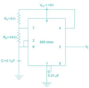
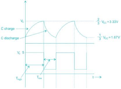
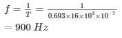
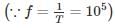
The frequency of oscillation of the astable multivibrator circuit given below is ______
Detailed Solution: Question 7
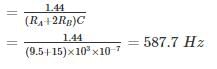
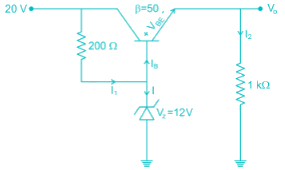
For the given circuit, what is the value of power dissipated in zener diode ?
Detailed Solution: Question 8
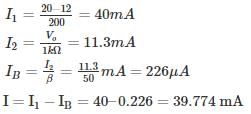
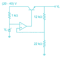
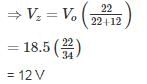
The output voltage of the voltage regulator is constant at 18.5 V. Assuming the op-amp and Zener diode are ideal, the maximum power dissipated in the transistor is ______ mw. The transistor β is very high.
Detailed Solution: Question 9

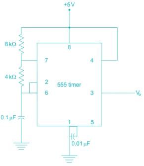
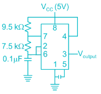
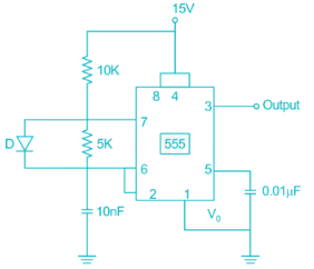
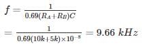
For the timer circuit shown below the frequency of oscillation is __________ kHz.
Detailed Solution: Question 10

135 videos|183 docs|71 tests |