Capacitance MCQ Level - 2 - Physics MCQ
10 Questions MCQ Test Topic wise Tests for IIT JAM Physics - Capacitance MCQ Level - 2
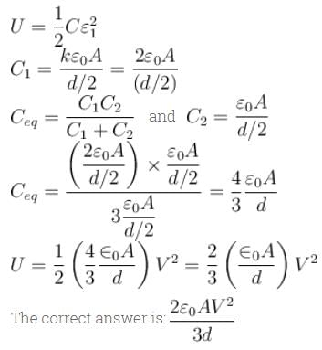
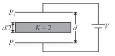
In the figure shown a parallel plate capacitor has a dielectric of width d/2 and dielectric constant K = 2. The other dimensions of the dielectric are same as that of the plates. The plates P1 and P2 the capacitor have area A each. The energy of the capacitor is :

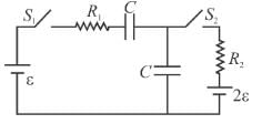
In the circuit shown, switch S2 is closed first and is kept closed for a long time. Now S1 is closed. Just after that instant the current through S1 is :

| 1 Crore+ students have signed up on EduRev. Have you? Download the App |
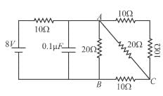
A capacitor of capacitance 0.1µF is connected to a battery of emf 8V as shown in the figure. Under steady state condition.

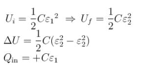
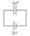
In the figure a capacitor of capacitance 2µF is connected to a cell of emf 20volt. The plates of the capacitor are drawn apart slowly to double the distance between them. The work done by the external agent on the plates is :
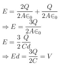
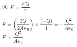
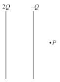
In the figure shown the plates of a parallel plate capacitor have unequal charges. Its capacitance is C. P is a point outside the capacitor and close to the plate of charge –Q. The distance between the plates is d select incorrect alternative :
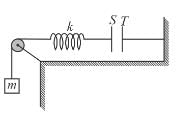
The plates S and T of an uncharged parallel plate capacitor are connected across a battery. The battery is then disconnected and the charged plates are now connected in a system as shown in the figure. The system shown is in equilibrium. All the strings and springs are insulating and massless. The magnitude of charge on one of the capacitor plate is :
(Area of plate = A)
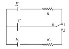
The key K (figure) is connected in turn to each of the contacts over short identical time intervals so that the change in the charge on the capacitor over each connection is small. The final charge qr on the capacitor is :
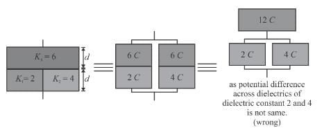
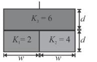
A parallel plate capacitor of capacitance C (without dielectrics) is filled by dielectric slabs as shown in the figure. Then the new capacitance of the capacitor is :
Initially switch S is connected to position 1 for a long time. The net amount of heat generated in the circuit after it is shifted to position 2 is


