Capacitance NAT Level - 1 - Physics MCQ
10 Questions MCQ Test Topic wise Tests for IIT JAM Physics - Capacitance NAT Level - 1
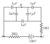
In the figure given, the potential difference (in Volts) between A and B in steady state will be

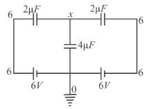
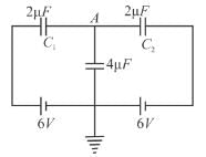
Three capacitors are connected as shown in figure. Then the charge (in µC) on capacitor plate C1 is :

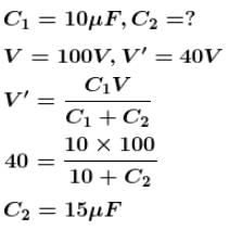
A capacitor of capacitance 10µF is charged to a potential of 100V. Now connecting it in parallel with an uncharged capacitor, the resultant potential difference becomes 40volt. The capacitance of this capacitor (in µF) is.
A 4µF capacitor is charged to 400volts and then its plates are joined through a resistor of resistance 1kΩ. The heat (in Joules) produced in the resistor is
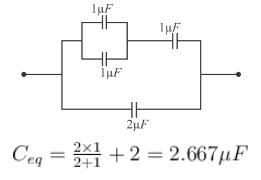
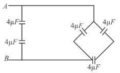
The equivalent capacitance (in µF) in the circuit shown in figure will be.
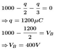
Two capacitors of 2µF and 3µF are connected in series. The potential at point A is 1000Volt and the outer plate of 3µF capacitor is earthed. The potential at point B is (in Volts).

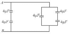
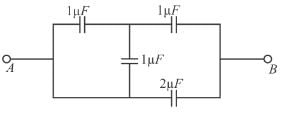
The equivalent capacitance (in µF) of the circuit shown, between points A and B will be.
What percentage of the energy drawn from the charging battery is stored in a capacitor.
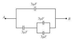
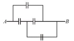
In the circuit shown in the figure, each capacitor has a capacity of 3µF. The equivalent capacity (in µF) between A and B is.
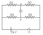
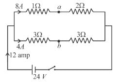
For the circuit shown in the diagram find the value of Va – Vb (in Volts) after long time closing the switch S1.
