Capacitance NAT Level - 2 - Physics MCQ
10 Questions MCQ Test Topic wise Tests for IIT JAM Physics - Capacitance NAT Level - 2
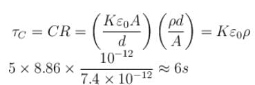
A leaky parallel plate capacitor is filled completely with a material having dielectric constant K = 5 and electrical conductivity σ = 7.4 × 10⁻¹²Ω–1m–1. If the charge on the capacitor at the instant t = 0 is q0 = 8.55µC, then calculate the leakage current (in µA) at the instant t = 12s.
In the figure shown find the equivalent capacitance between terminals A and B. The letters have their usual meaning capacitance is  Then x is.
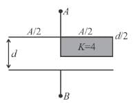
 Then x is.
| 1 Crore+ students have signed up on EduRev. Have you? Download the App |
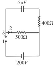
A capacitor of capacitance 5µF is connected to a source of constant emf of 200 V. Then the switch was shifted to contact 2 from contact 1. Find the amount of heat generated (in mJ) in the 400Ω resistance.

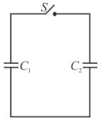
A 8µF capacitor C1 is charged to V0 = 120volt. The charging battery is then removed and the capacitor is connected in parallel to an uncharged +4µF capacitor C2.
What is the stored energy (in units of 10–2 J) before and after the switch S is closed?
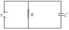
In the circuit shown, a time varying voltage V = 2000t volt is applied where t is second. At time t = 5ms, determine the current (in A) through the resistor R = 4Ω and through the capacitor C = 300µF.
A parallel plate capacitor is to be designed which is to be connected across 1kV potential difference. The dielectric material which is to be filled between the plates has dielectric constant K = 6π and dielectric strength 107V/m. For safely the electric field is never to exceed 10% of the dielectric strength. With such specifications, if we want a capacitor of capacitance 50pF, what minimum area (in mm2) of plates is required for safe working?

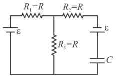
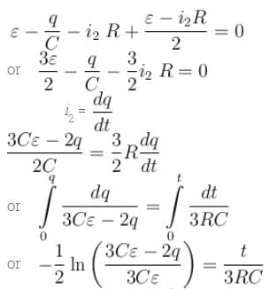
In the figure shown the capacitor is initially uncharged. The current in (R3 = R) at time t is  Find the value of (A + B)
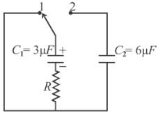
In the circuit shown a charged capacitor C1 = 3µF is discharged through R = 1kΩ by putting the switch is position 1. When the current reaches I0 = 2A, the switch is thrown to position 2 to discharge through uncharged capacitor C2 = 6µF and steady state is allowed to reach. Find the heat dissipated (in Joules) in the resistor R after switch is thrown to position 2.
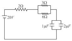
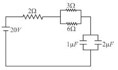
In the circuit shown the capacitors are initially uncharged. In a certain time the capacitor of capacitance 2µF gets a charge 20µC. In that time interval, find the heat produced (in µJ) in each resistor 6Ω.
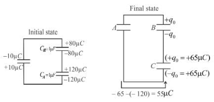
Given that CA = 1µF, CB = 2µF, and CC = 2µF, Initially each capacitor was charged to potential differences of VA = 10V, VB = 40V and VC = 60V separately and are kept as shown in figure (a). Now they are connected as shown in figure(b). The positive and negative sign shown in figure (b) represent initial polarities. If total amount of heat produced in µJ is given by (3100 – N) by the time steady state is reached find value of N.


