Electromagnetic Induction MCQ Level - 2 - Physics MCQ
10 Questions MCQ Test Topic wise Tests for IIT JAM Physics - Electromagnetic Induction MCQ Level - 2
An inductor L and a resistor R are connected in series with a direct current source of emf E. The maximum rate at which energy is stored in the magnitude field is :
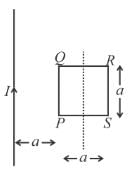
In the figure shown a square loop PQRS of side ‘a’ and resistance ‘r ’ is placed near an infinitely long wire carrying a constant current I. The sides PQ and RS are parallel to the wire. The wire and the loop are in the same plane. The loop is rotated by 180° about an axis parallel to the long wire and passing through the mid points of the side QR and PS. The total amount of charge which passes through any point of the loop during rotation is :

| 1 Crore+ students have signed up on EduRev. Have you? Download the App |
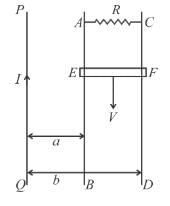
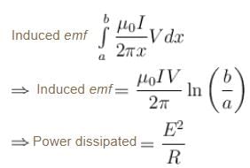
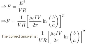
PQ is an infinite current carrying conductor. AB and CD are smooth conducting rods on which a conductor EF moves with constant velocity V as shown. The force needed to maintain constant speed of EF is :

A superconducting loop of radius R has self inductance L. A uniform and constant magnetic field B is applied perpendicular to the plane of the loop. Initially current in this loop is zero. The loop is rotated by 180°. The current in the loop after rotation is equal to :
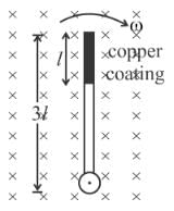
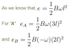
A wooden stick of length 3l is rotated about an end with constant angular velocity ω in a uniform magnetic field B perpendicular to the plane of motion. If the upper one third of its length is coated with copper, the potential across the whole length of the stick is
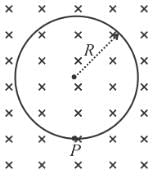
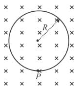
A uniform magnetic field of induction B is confined to a cylindrical region of radius R. The magnetic field is increasing at a constant rate of dB/dt (tesla/second). An electron of charge q, placed at the point P on the periphery of the field experiences an acceleration :
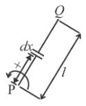
A rod of length l having uniformly distributed charge Q is rotated about one end with constant frequency ‘f ’. Its magnetic moment is :
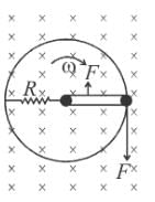
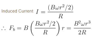
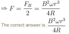
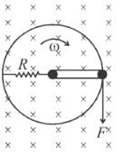
A metallic ring of mass m and radius r with a uniform metallic spoke of same mass m and length r is rotated about its axis with angular velocity ω in a perpendicular uniform magnetic field B as shown. If the central end of the spoke is connected to the rim of the wheel through a resistor R as shown. The resistor does not rotate, its one end is always at the center of the ring and other end is always in contact with the ring. A force F as shown is needed to maintain constant angular velocity of the wheel. F is equal to (The ring and the spoke has zero resistance)
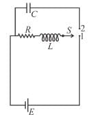
In the circuit shown in figure, the switch S was initially at position 1. After sufficiently long time, the switch S was thrown from position 1 to position 2. The voltage drop across the resistor at that instant is :
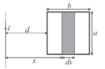
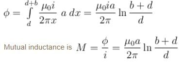
A rectangular loop of sides ‘a’ and ‘b’ is placed in xy plane. A very long wire is also placed in xy plane such that side of length ‘a’ of the loop is parallel to the wire. The distance between the wire and the nearest edge of the loop is ‘d ’. The mutual inductance of this system is proportional to :







 equivalent current di = f dq