Past Year Questions: Metrology And Inspection - Mechanical Engineering MCQ
30 Questions MCQ Test - Past Year Questions: Metrology And Inspection
The hole  and shaft,
  when assembled will result in
[ME 1987]
 and shaft,
  when assembled will result in
In an engineering drawing one finds the designation of 20G7f8, the position of tolerance of the hole is indicated by
[ME 1988]
| 1 Crore+ students have signed up on EduRev. Have you? Download the App |
A bush was turned after mounting the same on a mandrel. The mandrel diameter in millimeters is  and bore diameter of bush is
  The maximum eccentricity of the bush in mm will be
[ME 1991]
 and bore diameter of bush is
  The maximum eccentricity of the bush in mm will be
Two shafts A and B have their diameters specified as 100 ± 0.1 mm and 0.1 ± 0.0001 mm respectively. Which of the following statements is/are true
[ME 1992]
A shaft of diameter  mm and a hole of diameter
  mm when assembled would yield
[ME 1993]
The fit on a hole-shaft pair system is specified as H7-h6, the type of fit is
[ME 1996]
Allowance in limits and fits refers to
[ME 2001]
The dimensional limits on a shaft of 25h7are
[ME 2003]
In an interchangeable assembly, shafts of size  mm mate with holes of size
  mm. The maximum possible clearance in the assembly will be
[ME 2004]
GO and NO-GO plug gauges are to be designedfor a hole  mm. Gauge tolerances can be taken as 10% of the hole tolerance.Following ISO system of gauge design, sizes of GO and NO-GO gauge will be respectively.
[ME 2004]
In order to have interference fit, it is essential that the lower limit of the shaft should be
[ME 2005]
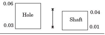
A hole is specified as  mm. The mating shaft has a clearance fit with minimum clearance of 0.01 mm. The tolerance on the shaft is 0.04 mm. The maximum clearance in mm between the hole and the shaft is
[ME 2007]
A shaft has a dimension,  respective values of fundamental deviation and tolerance are
[ME 2010]
A hole is of dimension  mm. The corresponding shaft is of dimension
  . The resulting assembly has
[ME 2011]
In an interchangeable assembly, shafts of size  mm mate with holes of size
  mm. The maximum interference (in microns) in the assembly is
[ME 2012]
Cylindrical pins of  mm diameter are electroplated in a shop. Thickness of the plating is
  micron. Neglecting gauge tolerance, the sized of the GO gage in mm to inspect the plated component is
[ME 2013]
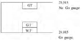
A Go-NO Go plug gauge is to be designed for measuring a hole of nominal diameter 25 mm with a hole tolerance of ± 0.015 mm. considering 10% of work tolerance to be the gauge tolerance and no wear condition, the dimension (in mm) of the GO plug gauge as per the unilateral tolerance system is
Holes of diameter  mm are assembled interchangeably with the pins of diameter
  mm. The minimum clearance in the assembly will be
[ME 2015,Set-1]
Which one of the following statements is TRUE?
[ME 2015,Set-2]
The most common limit gauge used for inspecting the hole diameter is
[ME 2019,Set-2]
The combination of slip gauges to obtain a dimension of 10.35 mm will be
[PI 1991]
A 30 mm hole shaft assembly results in minimum and maximum clearances of 0.03 mm and 0.30 mm respectively. The hole has a unilateral tolerance with zero fundamental deviation. If the tolerance on the shaft is 0.08 mm, the maximum size of the hole is
[PI 1992]
To obtain dimension of 61.18 mm using slip gauges, the most appropriate combination is
[PI 1992]
The maximum interference in mm after assembly between a bush of size  and a shaft of size
  is
is
[PI 1993]
Abbe's principle of alignment is used to be followed in
[PI 1995]
A keyway of 5 mm depth is to be milled in a shaft of diameter 60 ± 0.1 by positioning the shaft in a V-block of angle 120 deg and setting the tool with reference to the intersection of the face of the V-block. The error due to shaft tolerance which would be transferred on to the component is
[PI 2006]
Tolerance on the dimension x in the two component assembly shown below in (all dimension are in mm)
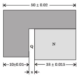
[PI 2007]
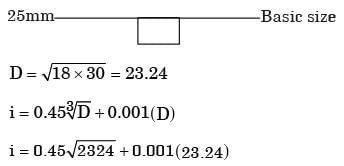
The following data are given for calculating limits of dimension and tolerances for a hole: Tolerance unit i (microns) = 0.45 (D1/3) + 0.001 D. The unit of D is mm. Diameter step is 18 – 30. If the fundamental deviation for hole H is zero and IT8 = 26i, the maximum and minimum limits of dimension for a 25H8 hole (in mm) are
[PI 2008]
A small bore is designated 25H7. The lower (minimum) and upper (maximum) limits of the . bore are 25.000 mm and 25.021 respectively.When the bore is designated as 25H8, then the upper limit is 25.033 mm. When the bore is designated as 25H6, then the upper limit of the bore in mm is
[PI 2010]
To measure the effective diameter of an external metric thread (included angle is 60°) of 3.5 mm pitch, a cylindrical standard of 30.5 mm diameter and two wires of 2 mm diameter each are used. The micrometer reading over the standard and over the wires are 16.532 mm and 15.398 mm respectively. The effective diameter (in mm) of the thread is
[PI 2011]


