Electronics and Communication Engineering (ECE) Exam  >  Electronics and Communication Engineering (ECE) Tests  >  GATE ECE (Electronics) Mock Test Series 2025  >  Test: Analog Electronics - 2 - Electronics and Communication Engineering (ECE) MCQ

Test: Analog Electronics - 2 - Electronics and Communication Engineering (ECE) MCQ


Test Description

20 Questions MCQ Test GATE ECE (Electronics) Mock Test Series 2025 - Test: Analog Electronics - 2

Test: Analog Electronics - 2 for Electronics and Communication Engineering (ECE) 2024 is part of GATE ECE (Electronics) Mock Test Series 2025 preparation. The Test: Analog Electronics - 2 questions and answers have been prepared according to the Electronics and Communication Engineering (ECE) exam syllabus.The Test: Analog Electronics - 2 MCQs are made for Electronics and Communication Engineering (ECE) 2024 Exam. Find important definitions, questions, notes, meanings, examples, exercises, MCQs and online tests for Test: Analog Electronics - 2 below.
Solutions of Test: Analog Electronics - 2 questions in English are available as part of our GATE ECE (Electronics) Mock Test Series 2025 for Electronics and Communication Engineering (ECE) & Test: Analog Electronics - 2 solutions in Hindi for GATE ECE (Electronics) Mock Test Series 2025 course. Download more important topics, notes, lectures and mock test series for Electronics and Communication Engineering (ECE) Exam by signing up for free. Attempt Test: Analog Electronics - 2 | 20 questions in 60 minutes | Mock test for Electronics and Communication Engineering (ECE) preparation | Free important questions MCQ to study GATE ECE (Electronics) Mock Test Series 2025 for Electronics and Communication Engineering (ECE) Exam | Download free PDF with solutions
Test: Analog Electronics - 2 - Question 1

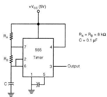
Shown below is a timer 555 IC circuit

Frequency of the waveform generated by the above circuit is 

Detailed Solution for Test: Analog Electronics - 2 - Question 1

Test: Analog Electronics - 2 - Question 2

The circuit shown in figure below represents:

Detailed Solution for Test: Analog Electronics - 2 - Question 2

It is just by figure only. But one can also calculate transfer function.

1 Crore+ students have signed up on EduRev. Have you? Download the App
*Answer can only contain numeric values
Test: Analog Electronics - 2 - Question 3

Consider the following feedback pair connection.
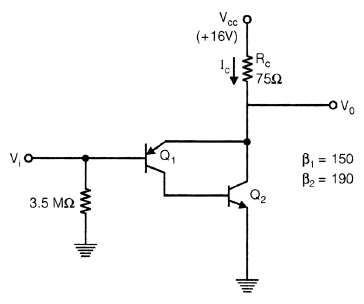
Collector current IC is ____________ mA.


Detailed Solution for Test: Analog Electronics - 2 - Question 3


Test: Analog Electronics - 2 - Question 4

If for a given programmable OPAMP, G1 is the gain, when only S1 is closed and G2 is the gain when only S2 is closed, then relation between G1 & G2 is?

Detailed Solution for Test: Analog Electronics - 2 - Question 4

When S1 is closed G1 = 1 it behaves like a voltage follower circuit. When S2 s closed

Test: Analog Electronics - 2 - Question 5

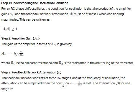
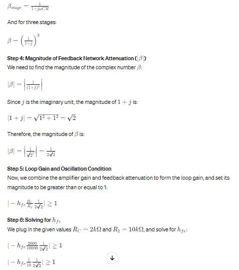
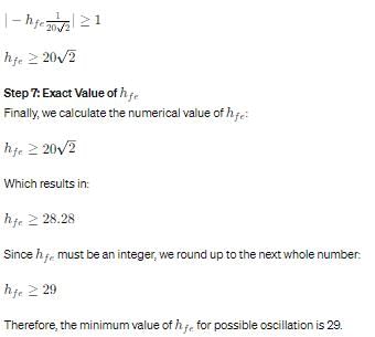
For given RC − Phase shift oscillator, by use of BJT if R1 = R2 = 10k, Rc = 2K, R = 2K, C = 0.01 µF

Q. 

What is Minimum value of hfe for possible oscillation? 

Detailed Solution for Test: Analog Electronics - 2 - Question 5

Test: Analog Electronics - 2 - Question 6

For given RC − Phase shift oscillator, by use of BJT if R1 = R2 = 10k, Rc = 2K, R = 2K, C = 0.01 µF

Q. 

What is frequency of oscillation for circuit? 

Detailed Solution for Test: Analog Electronics - 2 - Question 6

Test: Analog Electronics - 2 - Question 7

For a given CE, amplifier if β = 100, IC = 1 mA, RS = 1 KΩ, Rc = 5 KΩ, Re = 200 Ω, hie = 2.5 K.


Q. 

Calculate value of voltage gain

Detailed Solution for Test: Analog Electronics - 2 - Question 7


Test: Analog Electronics - 2 - Question 8

For a given CE, amplifier if β = 100, IC = 1 mA, RS = 1 KΩ, Rc = 5 KΩ, Re = 200 Ω, hie = 2.5 K.


Q. 

Calculate input impedance seen by source

Detailed Solution for Test: Analog Electronics - 2 - Question 8

Test: Analog Electronics - 2 - Question 9

For the given FET, circuit if

RD = 20 kΩ rd = 50 kΩ
RS = 2 kΩ µ = 50

Q.

Calculate value of v0/vs

Detailed Solution for Test: Analog Electronics - 2 - Question 9

Test: Analog Electronics - 2 - Question 10

For the given FET, circuit if

RD = 20 kΩ rd = 50 kΩ
RS = 2 kΩ µ = 50

Q. 

Calculate value of output impedance

Detailed Solution for Test: Analog Electronics - 2 - Question 10

Test: Analog Electronics - 2 - Question 11

The output voltage V0 for given circuit is

Detailed Solution for Test: Analog Electronics - 2 - Question 11

*Answer can only contain numeric values
Test: Analog Electronics - 2 - Question 12

A MOSFET amplifier circuit is as shown below:

If device parameter K = 15 µA/V2, then value of Transconductance of MOSFET is _________ ms.


Detailed Solution for Test: Analog Electronics - 2 - Question 12

Test: Analog Electronics - 2 - Question 13

The 3-terminal linear voltage regulator is connected to a 10 ohm load resistor as shown in figure. If Vin is 10 volt, what is power dissipated in the Si transistor.

Test: Analog Electronics - 2 - Question 14

A sinusoidal oscillator is built using an amplifier of real gain A, infinite input impedance and feedback (β) network is shown in figure. If Z = jX, then what is the value of z0.

Detailed Solution for Test: Analog Electronics - 2 - Question 14

Z+Z+Z0 =0 ⇒ Z0 = - 2jX

Test: Analog Electronics - 2 - Question 15

Shown below is a network, in collector feedback mode. 

Q.

The voltage gain Av is ……………., Assume re = 

Detailed Solution for Test: Analog Electronics - 2 - Question 15

Test: Analog Electronics - 2 - Question 16

Shown below is a network, in collector feedback mode. 

Q.

The current gain Ai is ≈ 

Detailed Solution for Test: Analog Electronics - 2 - Question 16

Test: Analog Electronics - 2 - Question 17

A power amplifier delivers 250 watt output at 50% efficiency. If ambient temp. is 25°C and maxm allowable junction temp. is 150°C, then what is value of Maximum thermal resistance which can be tolerated.

Detailed Solution for Test: Analog Electronics - 2 - Question 17

*Answer can only contain numeric values
Test: Analog Electronics - 2 - Question 18

Numerical Anser type question

Q.

For a BJT, CE-mode, Base to emitter capacitance (Cπ) is 10 times the collector to base capacitance (Cµ). If transistor is biased at quiescent collector current ICQ = 1 mA, and its short circuit unity gain frequency is 0.909 M rad/sec, then the value of Cπ is _______ nF.


Detailed Solution for Test: Analog Electronics - 2 - Question 18

Test: Analog Electronics - 2 - Question 19

In voltage reference diodes:

Detailed Solution for Test: Analog Electronics - 2 - Question 19

Voltage reference diode means zener diode

Test: Analog Electronics - 2 - Question 20

What should be values of components R & R2 such that frequency of wein-bridge oscillator is 300 HZ, if C = 0.01 µF, R1 = 12 kΩ.

Detailed Solution for Test: Analog Electronics - 2 - Question 20

25 docs|263 tests
Information about Test: Analog Electronics - 2 Page
In this test you can find the Exam questions for Test: Analog Electronics - 2 solved & explained in the simplest way possible. Besides giving Questions and answers for Test: Analog Electronics - 2, EduRev gives you an ample number of Online tests for practice

Top Courses for Electronics and Communication Engineering (ECE)

Download as PDF

Top Courses for Electronics and Communication Engineering (ECE)