Electrical Engineering (EE) Exam  >  Electrical Engineering (EE) Tests  >  Test: Analog Electronics - 2 - Electrical Engineering (EE) MCQ

Test: Analog Electronics - 2 - Electrical Engineering (EE) MCQ


Test Description

25 Questions MCQ Test - Test: Analog Electronics - 2

Test: Analog Electronics - 2 for Electrical Engineering (EE) 2024 is part of Electrical Engineering (EE) preparation. The Test: Analog Electronics - 2 questions and answers have been prepared according to the Electrical Engineering (EE) exam syllabus.The Test: Analog Electronics - 2 MCQs are made for Electrical Engineering (EE) 2024 Exam. Find important definitions, questions, notes, meanings, examples, exercises, MCQs and online tests for Test: Analog Electronics - 2 below.
Solutions of Test: Analog Electronics - 2 questions in English are available as part of our course for Electrical Engineering (EE) & Test: Analog Electronics - 2 solutions in Hindi for Electrical Engineering (EE) course. Download more important topics, notes, lectures and mock test series for Electrical Engineering (EE) Exam by signing up for free. Attempt Test: Analog Electronics - 2 | 25 questions in 25 minutes | Mock test for Electrical Engineering (EE) preparation | Free important questions MCQ to study for Electrical Engineering (EE) Exam | Download free PDF with solutions
Test: Analog Electronics - 2 - Question 1

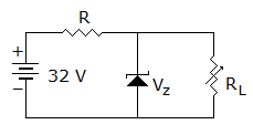
Figure is a 24 Vr stabilized power supply. The zener is 24 V, 600 mW. The minimum zener current is 10 mA. Proper values R and maximum load current are
Detailed Solution for Test: Analog Electronics - 2 - Question 1

Max. zener current = .

Maximum load current = 25 - 10 = 15 mA.

Test: Analog Electronics - 2 - Question 2

The open loop gain of an amplifier is 200. If negative feedback with β = 0.2 is used, the closed loop gain will be

Detailed Solution for Test: Analog Electronics - 2 - Question 2

Closed loop gain = .

1 Crore+ students have signed up on EduRev. Have you? Download the App
Test: Analog Electronics - 2 - Question 3

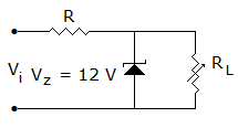
In figure as the load resistance is changed

Detailed Solution for Test: Analog Electronics - 2 - Question 3

Output voltage = 12 V, .

Test: Analog Electronics - 2 - Question 4

In a class C power amplifier the input signal has a frequency of 250 kHz. If the collector current pulses are 0.1 μs wide, the duty cycle of current waveform is

Detailed Solution for Test: Analog Electronics - 2 - Question 4

Test: Analog Electronics - 2 - Question 5

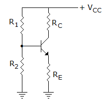
In figure, voltage across R2 = + 10 V. If VBE = 0.7 V and VE = 0.7 V and RE = 10 kΩ, current through RE is
Detailed Solution for Test: Analog Electronics - 2 - Question 5

Test: Analog Electronics - 2 - Question 6

A 12 kHz pulse wave-form is amplified by a circuit having an Upper cut-off frequency of 1 MHz. The minimum input pulse width that can be accurately reproduced is

Detailed Solution for Test: Analog Electronics - 2 - Question 6

tr = 10% Pω = minimum Power(P) = 10 tr 10 x 0.35 μ sec = 3.5 μ sec.

Note: The I/P Pulse will be severely distorted if the rise time is more than 10% of Pulse width.

Test: Analog Electronics - 2 - Question 7

Feedback factor may be less or more than 1.

Detailed Solution for Test: Analog Electronics - 2 - Question 7

Feedback factor is much less than 1.

Test: Analog Electronics - 2 - Question 8

An RC oscillator uses

Detailed Solution for Test: Analog Electronics - 2 - Question 8

One RC combination can give a phase shift of less them 90º. Therefore 3 RC combinations are required for 180º phase shift.

Test: Analog Electronics - 2 - Question 9

The main advantage of CMOS circuit is

Detailed Solution for Test: Analog Electronics - 2 - Question 9

Low power consumption is a big advantage in digital circuits.

Test: Analog Electronics - 2 - Question 10

Ac signals are given to both inverting and non-inverting terminals of an op-amp. When will the output maximum

Detailed Solution for Test: Analog Electronics - 2 - Question 10

For non-inverting terminal input, output is in phase with input. For inverting terminal input, output is 180º out of phase with input. If inputs have 180º phase difference, outputs will be in phase and additive.

Test: Analog Electronics - 2 - Question 11

An ideal op-amp has zero slew rate.

Detailed Solution for Test: Analog Electronics - 2 - Question 11

An ideal op-amp has infinitely fast slew rate.

Test: Analog Electronics - 2 - Question 12

In a bridge rectifier circuit the rms value of input ac voltage is 10 V. The PIV across each diode is

Detailed Solution for Test: Analog Electronics - 2 - Question 12

PIV is 2 x 10 = 14.14 V.

Test: Analog Electronics - 2 - Question 13

In a half wave diode rectifier circuit the current flows in the load circuit for

Detailed Solution for Test: Analog Electronics - 2 - Question 13

Current flows during positive half cycle.

Test: Analog Electronics - 2 - Question 14

In a push pull circuit

Detailed Solution for Test: Analog Electronics - 2 - Question 14

Since each transistor conducts for 180º. Therefore high efficiency but low distortion.

Test: Analog Electronics - 2 - Question 15

A transistor with a = 0.9 and ICBO = 10 μA is biased so that IBQ = 90 μA. Then IEQ will be

Detailed Solution for Test: Analog Electronics - 2 - Question 15

IEQ = ICQ + IBQ = 910 μA + 90 μA 990 μA.

Test: Analog Electronics - 2 - Question 16

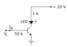
In figure, transistor βdc = 100 and LED voltage when it is conducting is 2 V. Then the base current which saturates the transistor is
Detailed Solution for Test: Analog Electronics - 2 - Question 16

.

Test: Analog Electronics - 2 - Question 17

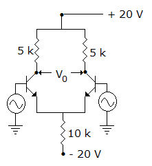
In figure the dc emitter current of each transistor is about
Detailed Solution for Test: Analog Electronics - 2 - Question 17

Total . It divides equally between the two transistors.

Test: Analog Electronics - 2 - Question 18

The input voltage for starting oscillations in an oscillator is caused by

Detailed Solution for Test: Analog Electronics - 2 - Question 18

The amplifier in the oscillator amplifies the noise voltages. However phase shift around the closed loop is zero at only one frequency. Therefore, only this frequency appears at output.

Test: Analog Electronics - 2 - Question 19

The current flowing in a certain P-N junction at room temperature is 2 x 10⁻⁷ Amp. When a large reverse biased voltage is applied. Calculate the current flowing when 0.1 volts is applied.

Detailed Solution for Test: Analog Electronics - 2 - Question 19

Test: Analog Electronics - 2 - Question 20

In following figure find VDSQ by assuming gate current is negligible for the p-channel JFET. (if IDQ = - 6 mA, RS = 0, VDD = -18 V, RD = 2 kΩ, IDSS = - 10 mA, IPO = - 3 V)

Detailed Solution for Test: Analog Electronics - 2 - Question 20

By Appling KVL around drain source loop.

VDSQ = -18 - (-6). 2 x 103 = - 18 + 12 k x 10-3 -6 V.

Test: Analog Electronics - 2 - Question 21

Which of the following power amplifiers has highest efficiency?

Detailed Solution for Test: Analog Electronics - 2 - Question 21

Class C has more efficiency than all other classes.

Test: Analog Electronics - 2 - Question 22

A full wave rectifier using centre tapped transformer and a bridge rectifier use similar diodes and have equal no load output voltage. Under equal load conditions

Detailed Solution for Test: Analog Electronics - 2 - Question 22

Since two diodes are in series bridge rectifier, voltage drop is more.

Test: Analog Electronics - 2 - Question 23

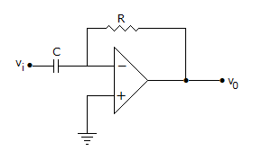
Assume that op-amp in figure is ideal. If input Vi is triangular, the output V0 will be
Detailed Solution for Test: Analog Electronics - 2 - Question 23

It is a differentiating amplifier.

Test: Analog Electronics - 2 - Question 24

In an amplifier with a gain of - 1000 and feedback factor β = - 0.1, the change in gain is 20% due to temperature. The change in gain for feedback amplifier will be

Detailed Solution for Test: Analog Electronics - 2 - Question 24

. When gain changes,

age change in

Test: Analog Electronics - 2 - Question 25

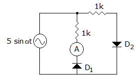
In the diode circuit of figure the diodes are ideal. The average current through ammeter is
Detailed Solution for Test: Analog Electronics - 2 - Question 25

.

Information about Test: Analog Electronics - 2 Page
In this test you can find the Exam questions for Test: Analog Electronics - 2 solved & explained in the simplest way possible. Besides giving Questions and answers for Test: Analog Electronics - 2, EduRev gives you an ample number of Online tests for practice

Top Courses for Electrical Engineering (EE)

Download as PDF

Top Courses for Electrical Engineering (EE)