Electrical Engineering (EE) Exam  >  Electrical Engineering (EE) Tests  >  Test: Analog Electronics - 5 - Electrical Engineering (EE) MCQ

Test: Analog Electronics - 5 - Electrical Engineering (EE) MCQ


Test Description

25 Questions MCQ Test - Test: Analog Electronics - 5

Test: Analog Electronics - 5 for Electrical Engineering (EE) 2024 is part of Electrical Engineering (EE) preparation. The Test: Analog Electronics - 5 questions and answers have been prepared according to the Electrical Engineering (EE) exam syllabus.The Test: Analog Electronics - 5 MCQs are made for Electrical Engineering (EE) 2024 Exam. Find important definitions, questions, notes, meanings, examples, exercises, MCQs and online tests for Test: Analog Electronics - 5 below.
Solutions of Test: Analog Electronics - 5 questions in English are available as part of our course for Electrical Engineering (EE) & Test: Analog Electronics - 5 solutions in Hindi for Electrical Engineering (EE) course. Download more important topics, notes, lectures and mock test series for Electrical Engineering (EE) Exam by signing up for free. Attempt Test: Analog Electronics - 5 | 25 questions in 25 minutes | Mock test for Electrical Engineering (EE) preparation | Free important questions MCQ to study for Electrical Engineering (EE) Exam | Download free PDF with solutions
Test: Analog Electronics - 5 - Question 1

A CB amplifier has a = 0.98 and RL = 600 Ω. If IE = 3.5 mA, the current gain is

Detailed Solution for Test: Analog Electronics - 5 - Question 1

Current gain of CB amplifier is a.

Test: Analog Electronics - 5 - Question 2

funity of an op-amp is about 1 kHz.

Detailed Solution for Test: Analog Electronics - 5 - Question 2

It is about 1 MHz.

1 Crore+ students have signed up on EduRev. Have you? Download the App
Test: Analog Electronics - 5 - Question 3

Assertion (A): In an RC coupled amplifier the junction capacitances can be neglected at low frequencies but not at high frequencies

Reason (R): Capacitive reactance is inversely proportional to frequency.

Detailed Solution for Test: Analog Electronics - 5 - Question 3

At high frequencies XC is very small.

Test: Analog Electronics - 5 - Question 4

In figure, D1 turns on when

Detailed Solution for Test: Analog Electronics - 5 - Question 4

D1 is forward biased when vi > V1.

Test: Analog Electronics - 5 - Question 5

In a full wave rectifier circuit using centre tapped transformer, the peak voltage across half of the secondary winding is 30 V. Then PIV is

Detailed Solution for Test: Analog Electronics - 5 - Question 5

In full wave circuit using centre tapped transformer PIV = 2Vm .

Test: Analog Electronics - 5 - Question 6

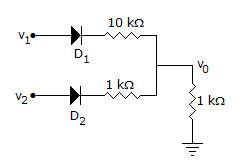
In the circuit of figure both diodes are ideal. If v1 = 10 V and v2 = 10 V which diode will conduct?
Detailed Solution for Test: Analog Electronics - 5 - Question 6

Both D1 and D2 are forward biased.

Test: Analog Electronics - 5 - Question 7

The output impedance of an ideal op-amp is

Detailed Solution for Test: Analog Electronics - 5 - Question 7

An ideal op-amp has zero output impedance and can deliver any amount of load current without any voltage drop.

Test: Analog Electronics - 5 - Question 8

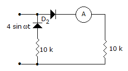
In the circuit of the given figure, assume that the diodes are ideal and the meter is an average indicating ammeter, the ammeter will read
Detailed Solution for Test: Analog Electronics - 5 - Question 8

Ammeter will real during +ve half cycle only and

.

Test: Analog Electronics - 5 - Question 9

A virtual ground is a ground for

Detailed Solution for Test: Analog Electronics - 5 - Question 9

No current can flow through virtual ground. However voltage is zero.

Test: Analog Electronics - 5 - Question 10

As compared to a full wave diode rectifier circuit using centre tapped transformer, the bridge diode rectifier circuit has the main advantage of

Detailed Solution for Test: Analog Electronics - 5 - Question 10

For bridge rectifier, peak inverse voltage is equal to peak value of ac voltage while for the circuit using centre tapped transformer peak inverse voltage is 2 Em.

Test: Analog Electronics - 5 - Question 11

A dc power supply has no load voltage of 30 V and full load voltage of 25 V at full load current of 1 A. The output resistance and voltage regulation respectively are

Detailed Solution for Test: Analog Electronics - 5 - Question 11

.

Test: Analog Electronics - 5 - Question 12

The main advantage of CC amplifier is

Detailed Solution for Test: Analog Electronics - 5 - Question 12

Therefore, it is suitable for impedance matching.

Test: Analog Electronics - 5 - Question 13

If a = 0.995, IE = 10 mA, ICO = 0.5 mA, then ICEO will be

Detailed Solution for Test: Analog Electronics - 5 - Question 13

.

Test: Analog Electronics - 5 - Question 14

Assertion (A): In class C amplifier the efficiency is more than that for other classes of amplifiers

Reason (R): In class C amplifier we can get high efficiency over a wideband

Detailed Solution for Test: Analog Electronics - 5 - Question 14

R is not correct because bandwidth of class C amplifier is narrow.

Test: Analog Electronics - 5 - Question 15

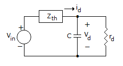
In the following figure C = 0.02 μF, and Vth is known to be of frequency ω = 107 rad/sec and rd = 2.5 Ω and ZTh = RTh = 10 Ω Then phase angle between id and Vd
Detailed Solution for Test: Analog Electronics - 5 - Question 15

Zd = (rd)11 (-jxd) 2 - JΩ

θ = tan-1 (-1/2) 26.56 .

Test: Analog Electronics - 5 - Question 16

A class C amplifier has input frequency of 200 kHz. If width of collector pulses is 0.1 μs, duty cycle is

Detailed Solution for Test: Analog Electronics - 5 - Question 16

.

Test: Analog Electronics - 5 - Question 17

Output of a phase splitter is

Detailed Solution for Test: Analog Electronics - 5 - Question 17

A phase shifter gives two voltages which have equal magnitudes but are out of phase by 180º.

Test: Analog Electronics - 5 - Question 18

In a transistor the minimum and maximum values of βdc are 100 and 121. The proper value of βdc to be used to locate Q point is

Test: Analog Electronics - 5 - Question 19

The input to an op-amp integrating amplifier is a constant voltage. The output will be

Detailed Solution for Test: Analog Electronics - 5 - Question 19

Integral of a constant is t.

Test: Analog Electronics - 5 - Question 20

FET amplifier is more difficult to analyse than BJT amplifier.

Detailed Solution for Test: Analog Electronics - 5 - Question 20

FET amplifier is easier to analyse since gate current is negligible.

Test: Analog Electronics - 5 - Question 21

To bypass a 100 ohm emitter resistor at

Detailed Solution for Test: Analog Electronics - 5 - Question 21

XC < 0.1 x 100 or XC < 10 Ω or 10 = or C 1000 mF.

Test: Analog Electronics - 5 - Question 22

In a CE amplifier the dc load line is the same as ac load line when

Detailed Solution for Test: Analog Electronics - 5 - Question 22

When ac collector resistance is very high, the net resistance is the same as dc collector resistance.

Test: Analog Electronics - 5 - Question 23

If the output current wave shape of class C circuit has a period of 1 μs and a pulse width of 0.006 μs, the duty cycle is

Detailed Solution for Test: Analog Electronics - 5 - Question 23

.

Test: Analog Electronics - 5 - Question 24

Which configuration is suitable for impedance matching?

Detailed Solution for Test: Analog Electronics - 5 - Question 24

CC has high input impedance and low output impedance. Hence suitable for impedance matching.

Test: Analog Electronics - 5 - Question 25

A BJT is said to be operating in saturation region if

Detailed Solution for Test: Analog Electronics - 5 - Question 25

For saturation both junctions have to be forward biased.

Information about Test: Analog Electronics - 5 Page
In this test you can find the Exam questions for Test: Analog Electronics - 5 solved & explained in the simplest way possible. Besides giving Questions and answers for Test: Analog Electronics - 5, EduRev gives you an ample number of Online tests for practice

Top Courses for Electrical Engineering (EE)

Download as PDF

Top Courses for Electrical Engineering (EE)