Electrical Engineering (EE) Exam  >  Electrical Engineering (EE) Tests  >  Test: Analog Electronics - 7 - Electrical Engineering (EE) MCQ

Test: Analog Electronics - 7 - Electrical Engineering (EE) MCQ


Test Description

25 Questions MCQ Test - Test: Analog Electronics - 7

Test: Analog Electronics - 7 for Electrical Engineering (EE) 2025 is part of Electrical Engineering (EE) preparation. The Test: Analog Electronics - 7 questions and answers have been prepared according to the Electrical Engineering (EE) exam syllabus.The Test: Analog Electronics - 7 MCQs are made for Electrical Engineering (EE) 2025 Exam. Find important definitions, questions, notes, meanings, examples, exercises, MCQs and online tests for Test: Analog Electronics - 7 below.
Solutions of Test: Analog Electronics - 7 questions in English are available as part of our course for Electrical Engineering (EE) & Test: Analog Electronics - 7 solutions in Hindi for Electrical Engineering (EE) course. Download more important topics, notes, lectures and mock test series for Electrical Engineering (EE) Exam by signing up for free. Attempt Test: Analog Electronics - 7 | 25 questions in 25 minutes | Mock test for Electrical Engineering (EE) preparation | Free important questions MCQ to study for Electrical Engineering (EE) Exam | Download free PDF with solutions
Test: Analog Electronics - 7 - Question 1

It is desired to reduce distortion in a CE amplifier circuit. We should

Test: Analog Electronics - 7 - Question 2

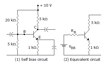
In the circuit of figure β = 50 and VBE = 0.5 V. The quiescent value of base current IB is
1 Crore+ students have signed up on EduRev. Have you? Download the App
Test: Analog Electronics - 7 - Question 3

For a push pull circuit the most favoured biasing method is

Test: Analog Electronics - 7 - Question 4

In feedback amplifier the closed loop gain is nearly independent of open loop gain and depends only on the feedback factor.

Test: Analog Electronics - 7 - Question 5

In a N-P-N transistor, when emitter junction is forward biased and collector junction is reverse biased, the transistor will operate in

Test: Analog Electronics - 7 - Question 6

A feedback network to be used with an amplifier to provide oscillation is tested and found to give an output of 0.124 V with a 0.5 V input. What percentage negative feedback should be introduced to the amplifier so that linear oscillations result?

Test: Analog Electronics - 7 - Question 7

The advantage of Weinbridge oscillator over the phase shift oscillator is that oscillator the frequency may be varied over a range of

Test: Analog Electronics - 7 - Question 8

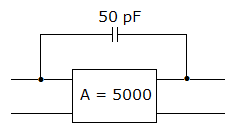
In figure the input and output Miller capacitances are
Test: Analog Electronics - 7 - Question 9

An inverting amplifier has R1 = 10 kΩ, and Rf = 150 kΩ then the O/P voltage, if input voltage Vi = 1 volt.

Test: Analog Electronics - 7 - Question 10

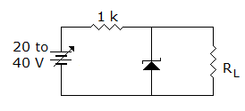
Figure uses 10 V zener diode. The minimum and maximum current through series resistance are
Detailed Solution for Test: Analog Electronics - 7 - Question 10

Minimum current = = 10 mA.

Minimum current = = 30 mA.

Test: Analog Electronics - 7 - Question 11

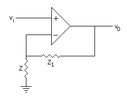
When Z1 << Z, The circuit of figure works as

Test: Analog Electronics - 7 - Question 12

In a class C operation VCC = 40 V, RL = 50 Ω. The maximum load power can be

Test: Analog Electronics - 7 - Question 13

IF VCC = 15 V, VCEQ = 5 V and ICQ = 50 mA, the efficiency in class A operation is

Test: Analog Electronics - 7 - Question 14

A bridge rectifier circuit has a dc load current of 10 mA and a filter capacitance of 1000 μF. The peak to peak ripple voltage is

Detailed Solution for Test: Analog Electronics - 7 - Question 14

Peak to peak ripple voltage = .

Test: Analog Electronics - 7 - Question 15

Which of the following best represents the bandwidth of an actual op-amp?

Test: Analog Electronics - 7 - Question 16

For an ideal noise free transistor amplifier the noise factor is

Test: Analog Electronics - 7 - Question 17

In a crystal

Test: Analog Electronics - 7 - Question 18

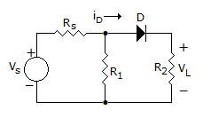
Voltage VL in the circuit when Vs < 0 where D is an ideal diode. (Take R1 = Rs = RL = 1 Ω)
Detailed Solution for Test: Analog Electronics - 7 - Question 18

if Vs ≥ 0, then id ≥ 0

if Vs < 0 then id < 0, Diode D is replaced by and open ckt and id = 0, hence VL = id . RL = 0.

Test: Analog Electronics - 7 - Question 19

Ultra high frequency oscillators work in the range

Test: Analog Electronics - 7 - Question 20

N-channel FETs are superior to p-channel FETs because

Test: Analog Electronics - 7 - Question 21

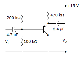
For the amplifier in figure, β = 800. The mid-band voltage gain V0/Vi is
Test: Analog Electronics - 7 - Question 22

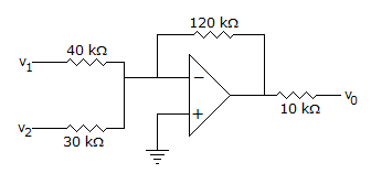
In the circuit of figure, v0 =

Test: Analog Electronics - 7 - Question 23

Class C amplifier is suitable for

Test: Analog Electronics - 7 - Question 24

In a N-P-N transistor, when emitter junction is forward biased and collector junction is reverse biased the transistor will operate in

Test: Analog Electronics - 7 - Question 25

A Wien bridge is suitable for

Information about Test: Analog Electronics - 7 Page
In this test you can find the Exam questions for Test: Analog Electronics - 7 solved & explained in the simplest way possible. Besides giving Questions and answers for Test: Analog Electronics - 7, EduRev gives you an ample number of Online tests for practice

Top Courses for Electrical Engineering (EE)

Download as PDF

Top Courses for Electrical Engineering (EE)