Electrical Engineering (EE) Exam  >  Electrical Engineering (EE) Tests  >  Topicwise Question Bank for Electrical Engineering  >  Test: Basic Laws- 2 - Electrical Engineering (EE) MCQ

Test: Basic Laws- 2 - Electrical Engineering (EE) MCQ


Test Description

15 Questions MCQ Test Topicwise Question Bank for Electrical Engineering - Test: Basic Laws- 2

Test: Basic Laws- 2 for Electrical Engineering (EE) 2025 is part of Topicwise Question Bank for Electrical Engineering preparation. The Test: Basic Laws- 2 questions and answers have been prepared according to the Electrical Engineering (EE) exam syllabus.The Test: Basic Laws- 2 MCQs are made for Electrical Engineering (EE) 2025 Exam. Find important definitions, questions, notes, meanings, examples, exercises, MCQs and online tests for Test: Basic Laws- 2 below.
Solutions of Test: Basic Laws- 2 questions in English are available as part of our Topicwise Question Bank for Electrical Engineering for Electrical Engineering (EE) & Test: Basic Laws- 2 solutions in Hindi for Topicwise Question Bank for Electrical Engineering course. Download more important topics, notes, lectures and mock test series for Electrical Engineering (EE) Exam by signing up for free. Attempt Test: Basic Laws- 2 | 15 questions in 45 minutes | Mock test for Electrical Engineering (EE) preparation | Free important questions MCQ to study Topicwise Question Bank for Electrical Engineering for Electrical Engineering (EE) Exam | Download free PDF with solutions
Test: Basic Laws- 2 - Question 1

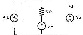
The current I in the circuit shown below is

Detailed Solution for Test: Basic Laws- 2 - Question 1

Let the current flowing through 5 Ω resistor be I' Applying KCL, we get
5 + I = I'.
Applying KVL, we get

So, 
= -4.4 A

Test: Basic Laws- 2 - Question 2

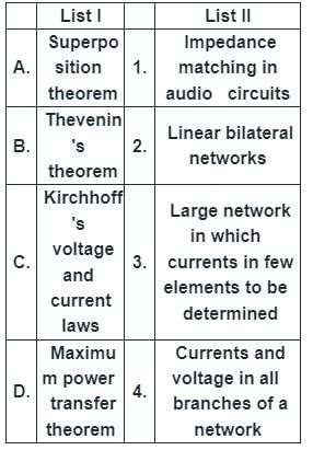
Match List I with List-II and select the correct answer using the code given below the lists:
Detailed Solution for Test: Basic Laws- 2 - Question 2

Explanation:

Superposition Theorem

  • It states that in any linear, active, bilateral network having more than one source, the response across any element is the sum of the responses obtained from each source considered separately and all other sources are replaced by their internal resistance.
  • The superposition theorem is used to solve the network where two or more sources are present and connected.
  • It can be applied to Linear bilateral networks.
  • The bilateral circuit allows the current flow in both directions.
  • The transmission line is the main example of the bilateral circuit because if you give a power supply from any direction, the circuit properties remain constant

Thevenin Theorem

  • It can be applied in complex or large networks to find current and voltage in few branches.
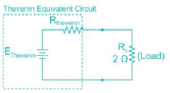
  • Thevenin’s Theorem states that it is possible to simplify any linear circuit, no matter how complex, to an equivalent circuit with just a single voltage source and series resistance connected to a load.

Kirchhoff's voltage and current laws

These are used to determine currents and voltage in all branches of a network.

The maximum power transfer theorem

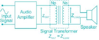
  • It helps in Impedance matching in audio circuits.
  • The Maximum Power Transfer Theorem is another useful circuit analysis method to ensure that the maximum amount of power will be dissipated in the load resistance when the value of the load resistance is exactly equal to the resistance of the power source. 

  • The maximum power transfer can be obtained even if the output impedance is not the same as the load impedance.
  • This can be done using a suitable “turns ratio” on the transformer with the corresponding ratio of load impedance.
Test: Basic Laws- 2 - Question 3

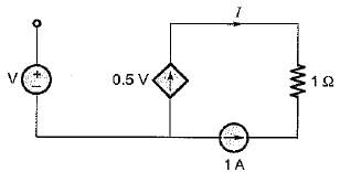
The value of current I in the circuit shown below for V = 2 volt is
Detailed Solution for Test: Basic Laws- 2 - Question 3

Applying KCL at the node connecting 0.5 V current source and 1 A current source, we get
1 + I = 0.5 V
For v - 2 volt, 1 + I = 1
or, I = 0 A

Test: Basic Laws- 2 - Question 4

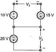
For the circuit shown below, the value of (V1+ V2) is

Detailed Solution for Test: Basic Laws- 2 - Question 4

Using KVL in the loop, we have
V= 10 + 15 = 25 volts
Also, V2 = -25 volts
∴ V1 + V2 = 25 - 25 = 0 volts

Test: Basic Laws- 2 - Question 5

The value of voltage source to be connected across the terminals X and Y so that drop across the 10 Ω resistor is 45 V is
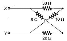
Detailed Solution for Test: Basic Laws- 2 - Question 5

Let the required voltage be V
Then, voltage across 10 Ω resistor

or,
Hence, required voltage is
V = 180 volts

Test: Basic Laws- 2 - Question 6

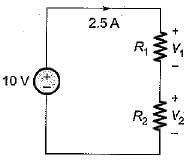
In a voltage divider circuit as shown below with two resistances R1 and R2, the voltage drop V1 is twice the drop V2 across R2. The value of R1, and R2 will be
Detailed Solution for Test: Basic Laws- 2 - Question 6

Using Ohm’s law,

Given, V1 = 2V2
As I is same therefore,
R1 = 2R2
∴ RT = R1 + R2 = 2R2 + R2 = 3R2
So, RT = 3R2 = 4Ω
or, 
and 

Test: Basic Laws- 2 - Question 7

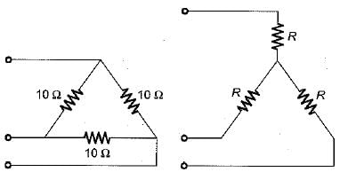
A delta connected load is shown in figure below. The equivalent star connection has a value of R in Ω is
Detailed Solution for Test: Basic Laws- 2 - Question 7

We know that
RΔ = 3 RY
or, 

Test: Basic Laws- 2 - Question 8

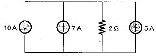
The voltage drop across the 2 Ω resistor for the circuit shown below is
Detailed Solution for Test: Basic Laws- 2 - Question 8

On combining the current sources, the circuit is reduced as shown below.

Hence, voltage drop across the 2Ω resistor
= 2 x 2 = 4 volts

Test: Basic Laws- 2 - Question 9

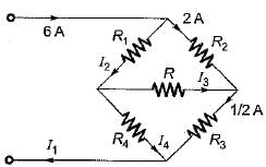
For the circuit shown below, the sum of the unknown currents I1, I2, l3 and I4 is
Detailed Solution for Test: Basic Laws- 2 - Question 9

Using KCL,
I2 = 6 - 2 = 4 A
Also, 
or, 
and I4 = I- I3 = 4 - (-1.5) = 5.5 A
Also, I1 = 6 A
∴ I1 + I2 + I3 + I4 = 6 + 4 - 1.5 + 5.5
= 15.5 - 1.5 = 14A 

Test: Basic Laws- 2 - Question 10

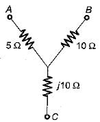
In the delta equivalent of the given star connected circuit is equal to

Detailed Solution for Test: Basic Laws- 2 - Question 10


= (10 + j10 + j20)
= (10 + j30) Ω

Test: Basic Laws- 2 - Question 11

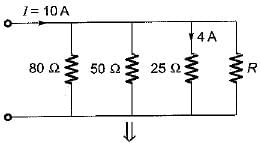
Four resistances 80 Ω, 50 Ω, 25 Ω and R are connected in parallel. Current through 25 Ω resistance is 4 A. The total current of the supply is 10 A. The value of R will be

Detailed Solution for Test: Basic Laws- 2 - Question 11


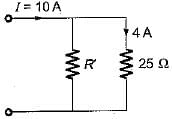
Given, I25Ω=4 A
Here, R' = 80║50║R


or, 
or, 

or, 29R + 400 = 40R or 11R = 400
or, R = 36.36 Ω

Test: Basic Laws- 2 - Question 12

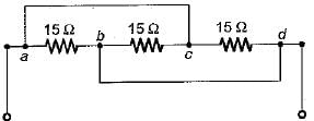
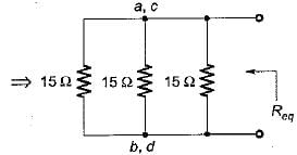
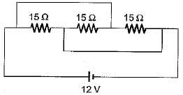
For the circuit shown below, the equivalent resistance will be
Detailed Solution for Test: Basic Laws- 2 - Question 12


Here, a and c are at equipotential.
Also, b and d are at equipotential
∴ 

Test: Basic Laws- 2 - Question 13

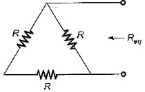
Three resistors of R Ω each are connected to form a triangle. The resistance between any two terminals will be

Detailed Solution for Test: Basic Laws- 2 - Question 13


Test: Basic Laws- 2 - Question 14

A network has 10 nodes and 17 branches. The number of different node pair voltage would be

Detailed Solution for Test: Basic Laws- 2 - Question 14

Number of different node-pair voltage = Number of KCL equations = n - 1 =10 - 1 = 9

Test: Basic Laws- 2 - Question 15

Kirchhoff's laws are not applicable to circuits with

212 tests
Information about Test: Basic Laws- 2 Page
In this test you can find the Exam questions for Test: Basic Laws- 2 solved & explained in the simplest way possible. Besides giving Questions and answers for Test: Basic Laws- 2, EduRev gives you an ample number of Online tests for practice
Download as PDF