Mechanical Engineering Exam  >  Mechanical Engineering Tests  >  Additional Study Material for Mechanical Engineering  >  Test: Bending Moment Diagram - Mechanical Engineering MCQ

Test: Bending Moment Diagram - Mechanical Engineering MCQ


Test Description

15 Questions MCQ Test Additional Study Material for Mechanical Engineering - Test: Bending Moment Diagram

Test: Bending Moment Diagram for Mechanical Engineering 2024 is part of Additional Study Material for Mechanical Engineering preparation. The Test: Bending Moment Diagram questions and answers have been prepared according to the Mechanical Engineering exam syllabus.The Test: Bending Moment Diagram MCQs are made for Mechanical Engineering 2024 Exam. Find important definitions, questions, notes, meanings, examples, exercises, MCQs and online tests for Test: Bending Moment Diagram below.
Solutions of Test: Bending Moment Diagram questions in English are available as part of our Additional Study Material for Mechanical Engineering for Mechanical Engineering & Test: Bending Moment Diagram solutions in Hindi for Additional Study Material for Mechanical Engineering course. Download more important topics, notes, lectures and mock test series for Mechanical Engineering Exam by signing up for free. Attempt Test: Bending Moment Diagram | 15 questions in 30 minutes | Mock test for Mechanical Engineering preparation | Free important questions MCQ to study Additional Study Material for Mechanical Engineering for Mechanical Engineering Exam | Download free PDF with solutions
Test: Bending Moment Diagram - Question 1

Which of the following is correct in bending moment diagram w.r.t the moment (M) of the force (F) acting on the body at a distance L from the axis of the rotation?

Detailed Solution for Test: Bending Moment Diagram - Question 1

The moment of the force about the axis of rotation by the application of the force on the body is given by the cross product of both. If the force not perpendicular to the axis, and making angle θ then cosine form of angle is used. As usually used in the cross product.

Test: Bending Moment Diagram - Question 2

What does the moment of the force measure in the bending moment diagram?

Detailed Solution for Test: Bending Moment Diagram - Question 2

The moment of the force measures the tendency of the rotation of the body along any axis, whether it be the centroid axis of the body, or any of the outside axis. The couple moment is produced by two forces, not by a single force. The total work done is the dot product of force and distance not the cross.

1 Crore+ students have signed up on EduRev. Have you? Download the App
Test: Bending Moment Diagram - Question 3

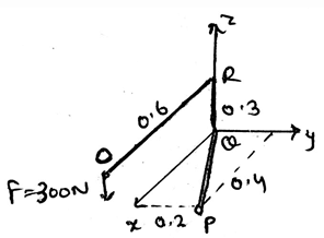
Determine the moment’s magnitude produce by the force as shown in the diagram, which tends to rotate the rod ORQP along QP.
Detailed Solution for Test: Bending Moment Diagram - Question 3

The use of the formula A.(rxF) gives the answer. In which A is 0.89i + 0.447j m. And the force is 300N, which is being applied at the end of the rod. Thus, after finding the equation of the axis and then replacing it in the equation shown above we get the answer. Actually, the main task is to know the axis equation in the vector form. Then get the magnitude of the moment.

Test: Bending Moment Diagram - Question 4

The moment of the force in bending moment diagram is the product of the force and the perpendicular distance of the axis and the point of action of the force.

Detailed Solution for Test: Bending Moment Diagram - Question 4

The moment is the product of the force applied to the body and the perpendicular distance of the point of action of the force to the axis about which the body is being rotated. That is the moment is the cross product of the force and the distance between the axis and the point of action.

Test: Bending Moment Diagram - Question 5

If any force is applied in the direction of the positive x-axis, and there are three different point in bending moment diagram on which the moment of this force is to be calculated. Then if these three points are on the positive side of the y-axis with varying distance, then what will be the direction of the moment caused by the force to the individual point?

Detailed Solution for Test: Bending Moment Diagram - Question 5

If you will apply he right hand rule on the system given then the right answer is the positive z-axis. Which is because the force is lying on the x-axis and is heading towards the positive infinity of the x-axis. And the points are in the positive y-axis. Apply the rule, and get the direction.

Test: Bending Moment Diagram - Question 6

Determine the moment of the force F along the segment QP of the pipe assembly shown in the figure.

Detailed Solution for Test: Bending Moment Diagram - Question 6

The use of the formula A.(rxF) gives the answer. In which A is 0.6i + 0.8j m and the r is 0.5i + 0.5k. And the force is 300N, which is being applied at the end of the rod. Thus, after finding the equation of the axis and then replacing it in the equation shown above we get the answer. Actually, the main task is to know the axis equation in the vector form. Then get the magnitude of the moment.

Test: Bending Moment Diagram - Question 7

Which of the following is true for bending moment diagram?

Detailed Solution for Test: Bending Moment Diagram - Question 7

The moment is the vector quantity. Thus the value of the total moment caused by various forces acting on the body is the vector sum of all the vectors. Also the moments are not perpendicular to each other, unless it is specified. Thus assumptions cant be taken for the direction of the moment.

Test: Bending Moment Diagram - Question 8

If you are getting to know about the direction of the moment caused by the force applied on the body by using your wrist and curling it in the direction of the rotation then which of the following is not right for bending moment diagram?

Detailed Solution for Test: Bending Moment Diagram - Question 8

The curled hand represents various thing. The direction of the moment axis is given by the thumb. The direction of the force is given by the fingers. As we place the fingers on the force and curl towards the rotational direction of the body about the axis.

Test: Bending Moment Diagram - Question 9

If the rotation is clockwise in this page, suppose, then in which direction will the thumb project if you curl your hand in the same direction of the rotation for bending moment diagram?

Detailed Solution for Test: Bending Moment Diagram - Question 9

As the curling will give the direction perpendicular to the paper. But it does depend upon the rotation sense. In this example, the sense is clockwise. Thus the thumb goes into the paper. That is it goes away from the viewer. Thus the answer.

Test: Bending Moment Diagram - Question 10

The tendency of rotation of the body along any axis in bending moment diagram is also called ___________

Detailed Solution for Test: Bending Moment Diagram - Question 10

The tendency of rotation of the body along any axis also called the torque. It is the moment of the force acting perpendicular to the direction of the axis of rotation. If the axis and the force are meeting at any point then there is no moment applied by the force.

Test: Bending Moment Diagram - Question 11

What does FLsinθ means/represents in bending moment diagram for the moment (M) of the force (F) acting on the body at a distance L from the axis of the rotation?

Detailed Solution for Test: Bending Moment Diagram - Question 11

The moment of the force about the axis of rotation by the application of the force on the body is given by the cross product of both. If the force not perpendicular to the axis, and making angle θ then cosine form of angle is used. Thus, FLsinθ represents the magnitude of the moment.

Test: Bending Moment Diagram - Question 12

The moment axis, force and the perpendicular distance in the bending moment diagram is lying in____________.

Detailed Solution for Test: Bending Moment Diagram - Question 12

The moment axis, force and the perpendicular distance is lying in the three dimensional Cartesian. It doesn’t lye on the single plane. It also doesn’t lye in a single line. Nor in the direction of the force. Thus they all lye in the planes which are perpendicular to each other.

Test: Bending Moment Diagram - Question 13

If a force applied at any point in its line of action and is still creating the same moment about any fixed point say P, then the force is said to be sliding vector. What is the name of this property in bending moment diagram?

Detailed Solution for Test: Bending Moment Diagram - Question 13

If a force applied at any point in its line of action and is still creating the same moment about any fixed point say P, then the force is said to be sliding vector. This is because the moment of the force which is acting on its line of axis at the point P is same throughout. This is known as the principle transmissibility of the force.

Test: Bending Moment Diagram - Question 14

The basic way of getting the direction of the moment caused by the force in bending moment diagram is:

Detailed Solution for Test: Bending Moment Diagram - Question 14

The basic way of doing so is to use right hand rule and not the left hand rule. The direction of the moment axis is given by the thumb. The direction of the force is given by the fingers. As we place the fingers on the force and curl towards the rotational direction of the body about the axis.

Test: Bending Moment Diagram - Question 15

If a force applied at any point in its line of action and is still creating the same moment about any fixed point say P, then the force in bending moment diagram is said to be______________

Detailed Solution for Test: Bending Moment Diagram - Question 15

If a force applied at any point in its line of action and is still creating the same moment about any fixed point say P, then the force is said to be sliding vector. This is because the moment of the force which is acting on its line of axis at the point P is same throughout. Whatever be the direction of the distance.

1 videos|30 docs|57 tests
Information about Test: Bending Moment Diagram Page
In this test you can find the Exam questions for Test: Bending Moment Diagram solved & explained in the simplest way possible. Besides giving Questions and answers for Test: Bending Moment Diagram , EduRev gives you an ample number of Online tests for practice

Top Courses for Mechanical Engineering

Download as PDF

Top Courses for Mechanical Engineering