Test: Controllers & Compensators - 2 - Electronics and Communication Engineering (ECE) MCQ
20 Questions MCQ Test - Test: Controllers & Compensators - 2

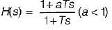
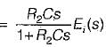
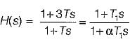
Assertion (A) : The phase lag network provides an attenuation of 20 log a (a < 1) at high frequencies having transfer function equal to

Reason (R): The lag network allows to pass high frequencies and low frequencies are attenuated.
Reason (R): The lag network allows to pass high frequencies and low frequencies are attenuated.
Assertion (A): Introduction of phase lag network in forward path increases the phase shift.
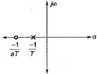
Reason (R): A phase lag network has pole nearer to the imaginary axis as compared to zero.
Reason (R): A phase lag network has pole nearer to the imaginary axis as compared to zero.

Match List-I (Type of controllers) with List-ll (Alternate names) and select the correct answer using the codes given below the lists:
List-I
A. Two-position controller
B. Proportional controller
C. Integral controller
D. Derivative controller
List-II
1. Rate controller
2. Reset controller
3. An amplifier with adjustable gain
4. ON-OFF controller
Codes:
A B C D
(a) 4 2 3 1
(b) 4 3 2 1
(c) 3 4 2 1
(d) 3 4 1 2
List-I
A. Two-position controller
B. Proportional controller
C. Integral controller
D. Derivative controller
List-II
1. Rate controller
2. Reset controller
3. An amplifier with adjustable gain
4. ON-OFF controller
Codes:
A B C D
(a) 4 2 3 1
(b) 4 3 2 1
(c) 3 4 2 1
(d) 3 4 1 2
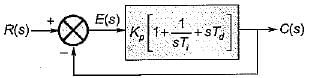
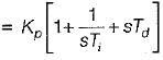
The open loop transfer function of a three action controller (PID controller) is given by
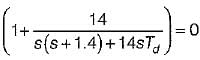
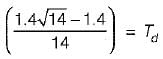
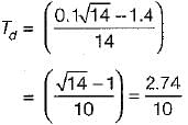
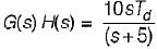
For the derivative feedback control shown in figure below, the damping ratio is equal to 0.7
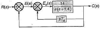
The value of derivative gain constant is
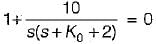
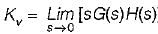
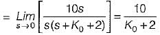
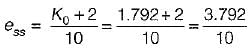
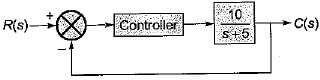
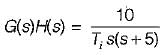
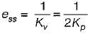
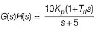
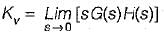
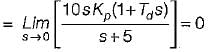
The block diagram of an integral control is shown in figure below.
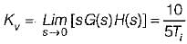
The steady state error in the above system for a parabolic input is

A system employing proportional plus error rate control is shown in figure below.
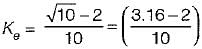
The value of error rate control (Ke) and 2% settling time for a damping ratio of 0.5 are respectively
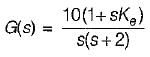
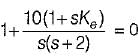

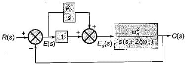
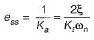
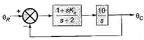
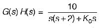
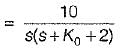
A feedback control system employing output- rate damping is shown in figure below.
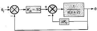
What is the steady state error (in radian) for the above system resulting from an unit ramp input if the damping ratio is 0.6?
In the control system shown below, the controller which can give infinite value of steady-stae error to a ramp input is
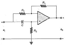
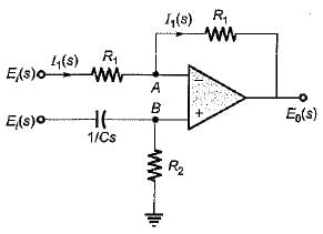
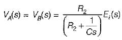
The transfer function of the OP-AMP circuit shown below is given by:
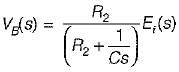
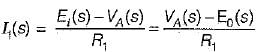
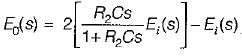 or,
or,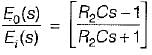
The transfer function of a phase lead compensator is given by  where α < 1 and T> 0.
Which of the following is not a correct value of maximum phase shift provided by such a compensator?
Assertion (A): Stepping motors are compatible with modern digital systems.
Reason (R): The nature of command is in the forms of pulses.
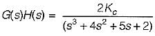
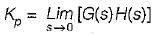
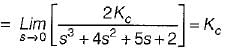
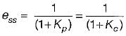
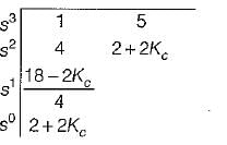
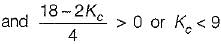
Consider the control system shown in figure below employing a proportional compensator.
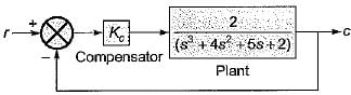
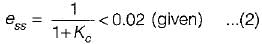
If the steady-state error has to be less than two percent for a unit step input, then the value of Kc would be
Match List-I (Controllers) with List-II (Transfer functions) and select the correct answer using the codes given below the lists:
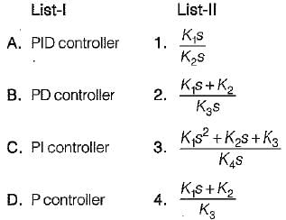
Codes:
A B C D
(a) 2 3 4 1
(b) 3 4 1 2
(c) 3 4 2 1
(d) 3 1 4 2
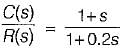
The transfer function of a system is given as:
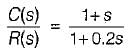
It represents a
The industrial controller having the best steady state accuracy is
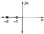
The transfer function of a phase lead controller is

The maximum value of phase shift provided by this controller is

With regard to the filtering property, the lead compensator and the lag compensators are respectively
Important Questions for Controllers & Compensators - 2
Controllers & Compensators - 2 MCQs with Answers
Online Tests for Controllers & Compensators - 2
|
© EduRev
|
Education Revolution
|


|


