1 Crore+ students have signed up on EduRev. Have you? |
Which type of transmission system is NOT considered for a DC system?
The DC transmission systems are classified as:
DC two-wire
DC two-wire with mid-point earthed
DC three-wire
(i) DC two-wire:
(ii) DC two-wire with mid-point earthed:
(iii) DC three-wire:
In a 3-wire DC system, there are two outers and a middle wire which is connected to earth.
When the load is balanced, the current in the neutral wire is zero.
DC 3- wire system is shown in figure below:
Conclusion:
From the above concept, it is clear that the DC four wires with line earthed are not considered for DC transmission.
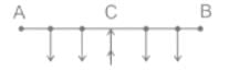
A 2-wire d.c. distributor 200 meters long is uniformly loaded with 2A/meter resistance of a single wire is 0.3 Ω/km. If the distributor is fed at one end, calculate the maximum voltage drop
Concept:
In a uniformly loaded distributor fed at one end, the maximum total voltage drop = IR/2
In a uniformly loaded distributor fed at both ends, the maximum total voltage drop = IR/8
The maximum voltage drop in the case of uniformly loaded distributor fed at both ends is one-fourth of the maximum voltage drop in the case of uniformly loaded distributor fed at one end.
Calculation:
Length of distributor = 200 m = 0.2 km
Current supplied by distributor = 2 amperes/meter
Total current supplied by distributor (I) = 200 × 2 = 400 A
The resistance of single wire = 0.3 Ω/km
Total resistance = 0.3 × 0.2 = 0.06 Ω
Maximum voltage drop
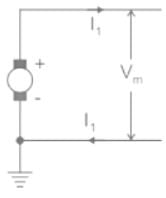
In a two-wire system, the voltage across the supply end is maintained at 500 V. The line is 4 km long. If the full-load current is 15 A, what should be the booster voltage and output so that the distant voltage can also be 500 V?
Take the resistance of the cable to be 0.5 ohm/km.
We Have,
Resistance of cable is 0.5 ohm/km
Hence, total Resistance of 4 km long cable (R) = 0.5 × 4 = 2 Ω
Load Current (I) = 15 A
So total Voltage drop in the cable = IR = 15 × 2 = 30 volts
Total Power Loss (P) = I2R
⇒ P = I2R = 152 × 2 = 225 × 2 = 450 W
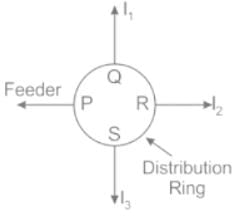
Which of the following is NOT a type of DC distributor?
Types Of DC Distributors:
Distributor Fed At One End:
Distributor Fed At Both Ends:
Distributor Fed At The Center:
Ring Main DC Distributor:
Two wire systems have the voltage at the supply end maintained at 500 V. The line is 4 km long. If the full-load current is 15 A, what must be the booster voltage and output in order that the far end voltage may also be 500 V. The resistance of the cable is 0.5 ohm/km.
Concept:
The booster output is given by:
W = Vb × Ifl
where, W = Booster output power
Vb = Booster voltage
Ifl = Full load current
Calculation:
Given, R = 0.5 ohm/km
RT = L × R
RT = 4 × 0.5 = 2Ω
Vb = Ifl × RT
Vb = 15 × 2
Vb = 30 V
W = 30 × 15
W = 450 W
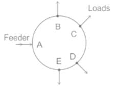
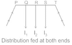
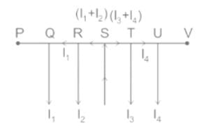
How many types of DC distributions system are present solely based on the way they are fed by feeders?
On the basis of how DC distributors are fed by the feeders, they are classified as:
Now the type of distribution given in the question is of type “Distributor fed at one end”.
Points to remember in this type of distribution:
The current in the various sections of the distributor away from the feeding point goes on decreasing. Thus the current in the section PQ is more than current in the section QR and the current in the section QR is more than current in section RS.
The voltage across the loads away from the feeding point goes on decreasing. Therefore minimum voltage occurs at point S.
In case a fault occurs at/on any section of the distributor, the whole distributor will have to be disconnected from the supply mains.
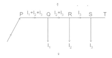
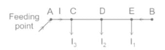
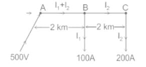
Fig. below shows a 2 wire DC distributor cable AC of 4 km long supplying loads of 100 A and 200 A at distances of 2 km and 4 km from A. The feeder is fed at point A with a voltage of 500 V. The voltage available at the farthest point in the system is ______.
(Assume conductor resistance per km as 0.02 Ω).
On the basis of how DC distributors are fed by the feeders, they are classified as:
Now the type of distribution given in the question is of type “Distributor fed at one end”.
Points to remember in this type of distribution:
Calculations:
Given- conductor resistance per km = 0.02 Ω
But in 2 wire DC distributor system 2 conductors are present
∴ Resistance per km for 2 wire DC distributor = 0.02 × 2 = 0.04 Ω
∴ Resistance of section AB = 0.04 × 2 = 0.08 Ω (RAB)
∴ Resistance of section BC = 0.04 × 2 = 0.08 Ω (RBC)
Also, I2 = 200 A, I1 = 100 A
∴ Current in section AB = I1 + I2 = 100 + 200 = 300 A
∴ current in section BC = I2 = 200 A
i.e. IAB = 300 A, IBC = 200 A
Now, Voltage available at load point B
VB = Voltage at A – Voltage drop in AB
VB = 500 V – IAB × RAB
VB = 500 V – (300 × 0.08) V
VB = (500 - 24) V
VB = 476 V
Now, voltage available at point C
VC = voltage at B – voltage drop in BC
VC = 476 V – IBC × RBC
VC = 476 V – (200 × 0.08) V
VC = 476 V – 16 V
VC = 460 V
Therefore the voltage available at the farthest point (C) in the system is 460 V.
Note:
There are a few advantages of other types of the distribution system.
Fig. Distributor fed at the center
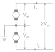
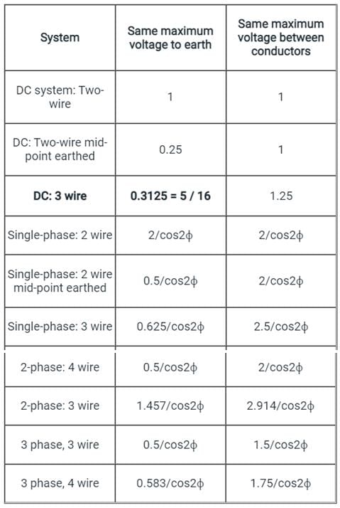
The amount of copper used by a 3-wire distributor having the same maximum voltage to earth as compared to a 2-wire DC distributor is ______.
Concept:
Important Points:
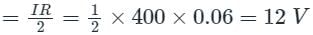
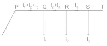
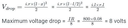
A 2-wire DC distributor cable 800 m long is loaded with 1 A/m. Resistance of each conductor is 0.05 Ω/km. Calculate the maximum voltage drop if the distributor is fed from both ends with equal voltages of 220 V.
Concept:
Total current supplied by the distributor, I = 800 × 1 = 800A
Total resistance of the distributor , R = 2 × 0.05 × 0.8 = 0.08 ohm
For a uniformly loaded DC-distributed wire fed from both sides with equal voltages, the Vmin occurs at mid-point( x = l/2).
So the maximum voltage drop is at the mid-point:
Calculation:
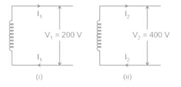
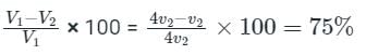
What is the percentage saving in feeder copper if the line voltage in a 2-wire DC systems is raised from 100 V to 200 V for the same power transmitted over the same power distance and having the same power loss?
Consider 200 V (Fig i) and 400 V (Fig ii) system as shown below:
We have,
P1 = V1I1 = 200I1 and P2 = V2I2 = 400I2
As the same power is delivered in both cases,
Therefore,
P1 = P2
200I1 = 400I2
I2 = 200/400 = 0.5I1
Now, power loss in 200V system (W1) = 2I12R1
And, power loss in 400V system ( W2) = 2I22R2 = 2(0.5I1)2R2 = 0.5I12R2
As power loss in the two cases is the same, W1 = W2
2I12R1 = 0.5I12R2;
⇒ R2/R1 = 4
We know resistance is inversely proportional to area.
Therefore: A1/A2 = 4, Also, ratio of volume ; v1/v2 = 4
⇒ v1 = 4v2
(Note: 'v' abbreviated for volume)
Hence,
Percentage Saving in copper =
42 docs|34 tests
|
Use Code STAYHOME200 and get INR 200 additional OFF
|
Use Coupon Code |
42 docs|34 tests
|
|
|
|
|
|
|
|
|