Test: Electromagnetic Induction - 2 - JEE MCQ
25 Questions MCQ Test - Test: Electromagnetic Induction - 2

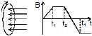
A wire loop is placed in a region of time varying magnetic field which is oriented orthogonally to the plane of the loop as shown in the figure. The graph shows the magnetic field variation as the function of time. Assume the positive emf is the one which drives a current in the clockwise direction and seen by the observer in the direction of B. Which of the following graphs best represents the induced emf as a function of time.
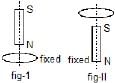
A vertical bar magnet is dropped from position on the axis of a fixed metallic coil as shown in fig-I. In fig-II the magnet is fixed and horizontal coil is dropped. The acceleration of the magnet and coil are a1 and a2 respectively then

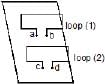
An electric current i1 can flow either direction through loop (1) and induced current i2 in loop (2). Positive i1 is when current is from `a' to `b' in loop (1) and positive i2 is when the current is from `c' to `d' in loop (2)
In an experiment, the graph of i2 against time `t' is as shown below

Which one(s) of the following graphs could have caused i2 to behave as give above.
Figure shows a bar magnet and a long straight wire W, carrying current into the plane of paper. Point P is the point of intersection of axis of magnet and the line of shortest distance between magnet and the wire. If p is the midpoint of the magnet, then which of the following statements is correct ?

A negative charge is given to a nonconducting loop and the loop is rotated in the plane of paper about its centre as shown in figure. The magnetic field produced by the ring affects a small magnet placed above the ring in the same plane :

Figure shown plane figure made of a conductor located in a magnetic field along the inward normal to the plane of the figure. The magnetic field starts diminishing. Then the induced current
A conducting wire frame is placed in a magnetic field which is directed into the paper. The magnetic field is increasing at a constant rate. The directions of induced currents in wires AB and CD are

A bar magnet is moved along the axis of copper ring placed far away from the magnet. Looking from the side of the magnet, an anticlockwise current is found to be induced in the ring. Which of the following may be true?
Two circular coils P & Q are fixed coaxially & carry currents I1 and I2 respectively

Which of the following quantities can be written in SI units in K gm2 A-2 S-3 ?
AB and CD are smooth parallel rails, separated by a distance l, and inclined to the horizontal at an angle q. A uniform magnetic field of magnitude B, directed vertically upwards, exists in the region. EF is a conductor of mass m, carrying a current i. For EF to be in equilibrium,
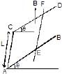
AB and CD are smooth parallel rails, separated by a distance l, and inclined to the horizontal at an angle q. A uniform magnetic field of magnitude B, directed vertically upwards, exists in the region. EF is a conductor of mass m, carrying a current i. if B is normal to the plane of the rails
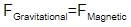
A conducting rod PQ of length L = 1.0 m is moving with a uniform speed v = 20 m/s in a uniform magnetic field B = 4.0 T directed into the paper. A capacitor of capacity C = 10 mF is connected as shown in figure. Then
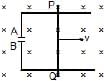
two different arrangements in which two square wire frames of same resistance are placed in a uniform constantly decreasing magnetic field B.

The value of magnetic flux in each case is given by
Two different arrangements in which two square wire frames of same resistance are placed in a uniform constantly decreasing magnetic field B.
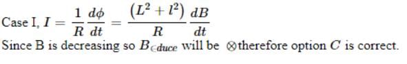
The direction of induced current in the case I is
Two different arrangements in which two square wire frames of same resistance are placed in a uniform constantly decreasing magnetic field B.
The direction of induced current in the case II is
Two different arrangements in which two square wire frames of same resistance are placed in a uniform constantly decreasing magnetic field B.
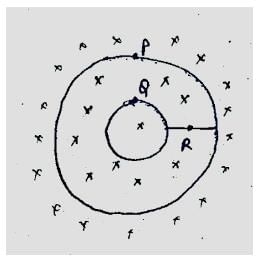
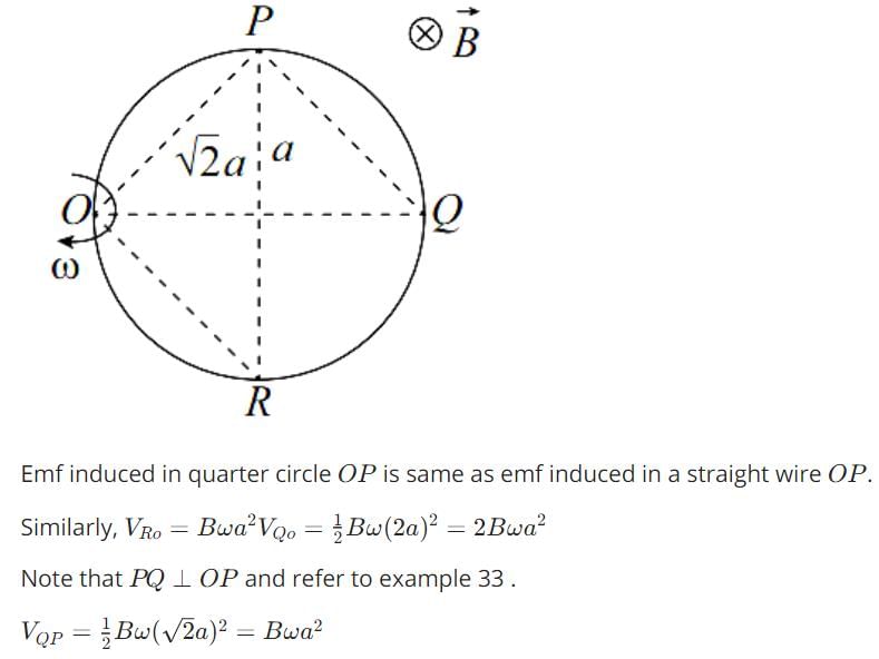
A conducting ring of radius a is rotated about a point O on its periphery as shown in the figure in a plane perpendicular to uniform magnetic field B which exists everywhere. The rotational velocity is w.
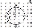
Choose the correct statement(s) related to the potential of the points P, Q and R
A conducting ring of radius a is rotated about a point O on its periphery as shown in the figure in a plane perpendicular to uniform magnetic field B which exists everywhere. The rotational velocity is w.
A conducting ring of radius a is rotated about a point O on its periphery as shown in the figure in a plane perpendicular to uniform magnetic field B which exists everywhere. The rotational velocity is w.
Choose the correct statement(s) related to the induced current in ring
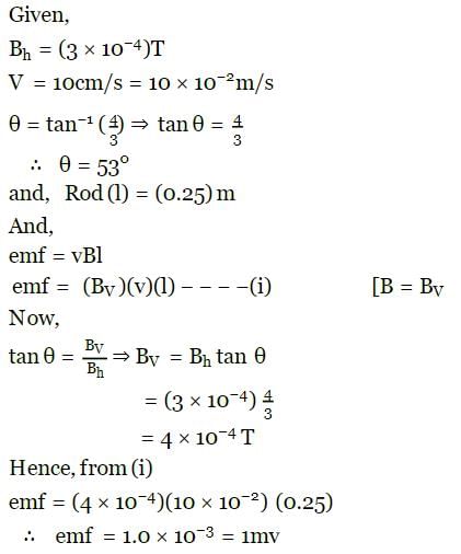
The horizontal component of the earth's magnetic field at a place is 3 × 10⁻⁴ T and the dip is tan-1(4/3). A metal rod of length 0.25 m placed in the north-south position is moved at a constant speed of 10 cm/s towards the east. Find the e.m.f induced in the rod. in mV
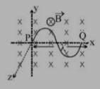
A wire forming one cycle of sine curve is moved in x-y plane with velocity 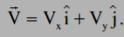 . There exist a magnetic field
  . Find the motional emf develop across the ends PQ of wire.
A conducting circular loop is placed in a uniform magnetic field of 0.02 T, with its plane perpendicular to the field. If the radius of the loop starts shrinking at a constant rate of 1.0 mm/s, then find the emf induced in the loop, at the instant when the radius is 4 cm.
Find the dimension of the quantity  , where symbols have usual meaning.
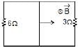
A rectangular loop with a sliding connector of length l = 1.0 m is situated in a uniform magnetic field B = 2T perpendicular to the plane of loop. Resistance of connector is r = 2W. Two resistances of 6W and 3W are connected as shown in figure. Find the external force required to keep the connector moving with a constant velocity v = 2m/s.
Important Questions for Electromagnetic Induction - 2
Electromagnetic Induction - 2 MCQs with Answers
Online Tests for Electromagnetic Induction - 2
|
© EduRev
|
Education Revolution
|


|


within 7 days!