Electronics and Communication Engineering (ECE) Exam  >  Electronics and Communication Engineering (ECE) Tests  >  GATE ECE (Electronics) Mock Test Series 2025  >  Test: Feedback Amplifiers - Electronics and Communication Engineering (ECE) MCQ

Test: Feedback Amplifiers - Electronics and Communication Engineering (ECE) MCQ


Test Description

10 Questions MCQ Test GATE ECE (Electronics) Mock Test Series 2025 - Test: Feedback Amplifiers

Test: Feedback Amplifiers for Electronics and Communication Engineering (ECE) 2024 is part of GATE ECE (Electronics) Mock Test Series 2025 preparation. The Test: Feedback Amplifiers questions and answers have been prepared according to the Electronics and Communication Engineering (ECE) exam syllabus.The Test: Feedback Amplifiers MCQs are made for Electronics and Communication Engineering (ECE) 2024 Exam. Find important definitions, questions, notes, meanings, examples, exercises, MCQs and online tests for Test: Feedback Amplifiers below.
Solutions of Test: Feedback Amplifiers questions in English are available as part of our GATE ECE (Electronics) Mock Test Series 2025 for Electronics and Communication Engineering (ECE) & Test: Feedback Amplifiers solutions in Hindi for GATE ECE (Electronics) Mock Test Series 2025 course. Download more important topics, notes, lectures and mock test series for Electronics and Communication Engineering (ECE) Exam by signing up for free. Attempt Test: Feedback Amplifiers | 10 questions in 30 minutes | Mock test for Electronics and Communication Engineering (ECE) preparation | Free important questions MCQ to study GATE ECE (Electronics) Mock Test Series 2025 for Electronics and Communication Engineering (ECE) Exam | Download free PDF with solutions
Test: Feedback Amplifiers - Question 1

Which of these doesn’t refer to a series-shunt feedback?

Detailed Solution for Test: Feedback Amplifiers - Question 1

In a series shunt feedback network, feedback is connected in series with signal source but in shunt with the load. Error voltage from feedback network is in series with the input. Voltage fed back from output is proportional to output voltage, hence parallel or shunt connected. The current in and voltage out connection refers to a shunt-shunt connection.

Test: Feedback Amplifiers - Question 2

Given that a feedback network is shunt-series, and output load is 10kΩ, what is the output voltage across it given that transfer gain is 10, source current is 20mA and feedback current is 10mA?

Detailed Solution for Test: Feedback Amplifiers - Question 2

RL = 10kΩ
IF = βIL
IL = IF/β = 10/10 = 1mA
VL = ILRL = 10V.

1 Crore+ students have signed up on EduRev. Have you? Download the App
Test: Feedback Amplifiers - Question 3

Consider a voltage series feedback network, where amplifier gain = 100, feedback factor = 5. For the basic amplifier, input voltage = 4V, input current=2mA. Find the input resistance of the network.

Detailed Solution for Test: Feedback Amplifiers - Question 3

RI = VI/II = 4/2m = 2kΩ
RIF = RI(1+A.β) = 2k(1+500) = 1002kΩ.

Test: Feedback Amplifiers - Question 4

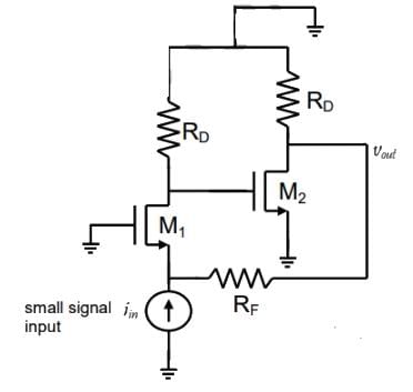
Consider the circuit shown below.
Circuit contains Current-shunt feedback & Current-series feedback
Consider A: Current-shunt feedback
B: Current-series feedback
C: Voltage-shunt feedback
D: Voltage-series feedback
Which of the above are present?

Detailed Solution for Test: Feedback Amplifiers - Question 4

Resistor R5 causes global feedback. It is connected to the input node, causing shunt mixing but not to output node, meaning current sampling. Hence it’s a current shunt feedback. Resistors R6 and R7 are neither connected to input nor the output, causing series mixing and current sampling, hence causing current series feedback.

Test: Feedback Amplifiers - Question 5

In a feedback network, input voltage is 14V, feedback voltage is 6V and source voltage is 20V. β is in ohms. What is its configuration?

Detailed Solution for Test: Feedback Amplifiers - Question 5

Given that input is 14V, feedback is 6V and source is 20 V, we can see
VI = VS – VF, which is voltage mixing. Also, β is in ohms that is voltage/current. Since output of feedback is voltage and input is current, the output has current sampling. Thus, configuration is a series-series feedback/current – series feedback.

Test: Feedback Amplifiers - Question 6

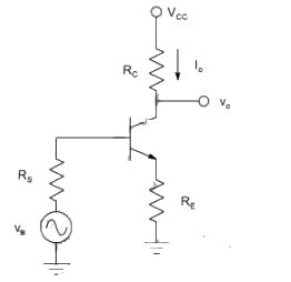
In the following diagram, shaded portions are named A and B.
Find the Shaded portions are named A & B
What are A and B?

Detailed Solution for Test: Feedback Amplifiers - Question 6

When feedback network is in shunt with load, then output voltage appears as input to feedback. In above case, output current appears as the feedback input, hence B is a current sampling network. Also, feedback network is in shunt with the signal source, hence it’s called shunt mixing or current mixing.

Test: Feedback Amplifiers - Question 7

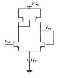
Consider the circuit shown.
Type of sampling observed is Series-Shunt feedback
What is the type of sampling observed?

Detailed Solution for Test: Feedback Amplifiers - Question 7

The feedback network is connected directly to output node, so voltage sampling occurs. However, it’s not connected directly to the input node. Hence it’s series mixing at the input. Voltage sampling is a shunt network.

Test: Feedback Amplifiers - Question 8

In which network is the unit of the feedback factor Ω?

Detailed Solution for Test: Feedback Amplifiers - Question 8

In series-series feedback, the output is current sampled, that is it is in series with the load. Also, input is a voltage mixer, which is in series with signal source. So feedback factor
Β = VF/IL in Ohms.

Test: Feedback Amplifiers - Question 9

What is the reverse transmission factor?

Detailed Solution for Test: Feedback Amplifiers - Question 9

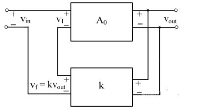
In feedback systems, the feedback signal is in proportion with the output signal.
XF ∝ XO
XF = βXO, where β is the feedback factor or reverse transmission factor.

Test: Feedback Amplifiers - Question 10

Consider an open loop circuit with lower cutoff frequency 5kHz and upper cutoff frequency 20kHz. If negative feedback is applied to the same, choose correct option stating the new cutoff frequencies.

Detailed Solution for Test: Feedback Amplifiers - Question 10

Negative feedback decreases lower cutoff frequencies and increases the higher cutoff frequency.
fHF = fH(1+Aβ)
fLF = fL/(1+Aβ)
Total bandwidth is thus increased.

25 docs|263 tests
Information about Test: Feedback Amplifiers Page
In this test you can find the Exam questions for Test: Feedback Amplifiers solved & explained in the simplest way possible. Besides giving Questions and answers for Test: Feedback Amplifiers, EduRev gives you an ample number of Online tests for practice

Top Courses for Electronics and Communication Engineering (ECE)

Download as PDF

Top Courses for Electronics and Communication Engineering (ECE)