Logic Gates - 2 - Free MCQ Practice Test with solutions, GATE EE Digital
MCQ Practice Test & Solutions: Test: Logic Gates - 2 (15 Questions)
You can prepare effectively for Electrical Engineering (EE) Digital Electronics with this dedicated MCQ Practice Test (available with solutions) on the important topic of "Test: Logic Gates - 2". These 15 questions have been designed by the experts with the latest curriculum of Electrical Engineering (EE) 2026, to help you master the concept.
Test Highlights:
- - Format: Multiple Choice Questions (MCQ)
- - Duration: 45 minutes
- - Number of Questions: 15
Sign up on EduRev for free to attempt this test and track your preparation progress.

Detailed Solution: Question 1
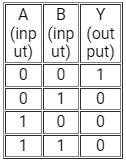
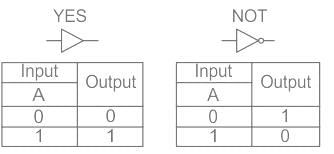
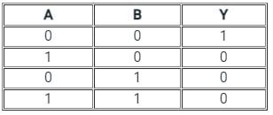
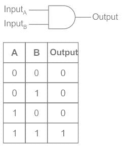
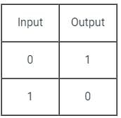
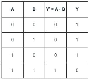
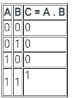
The truth table given below is for
(A and B are the inputs, Y is the output)
(A and B are the inputs, Y is the output)
Detailed Solution: Question 2

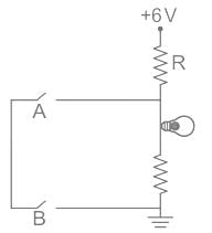
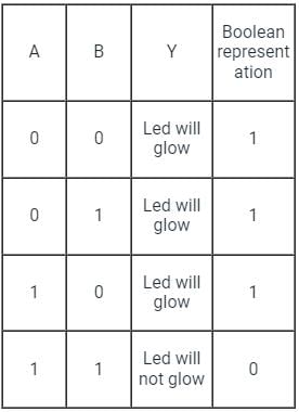
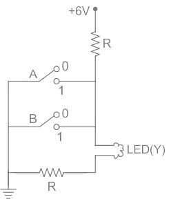
If the glow of the bulb is considered an output, the correct Boolean operation represented by the circuit diagram drawn will be:
If the glow of the bulb is considered an output, the correct Boolean operation represented by the circuit diagram drawn will be:
Detailed Solution: Question 3
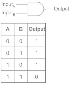
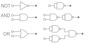
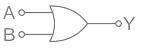
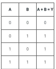
The circuit diagram shown here corresponds to the logic gate
Detailed Solution: Question 4
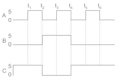
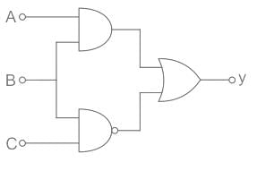
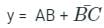
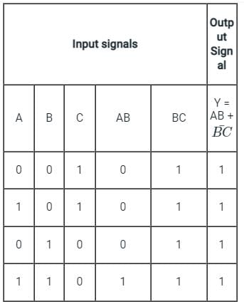
For the given circuit, the input digital signals are applied at the terminals A, B and C. What would be the output at the terminal y ?
Detailed Solution: Question 5
Detailed Solution: Question 6
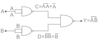
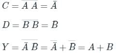
When both the input signals A and B of the NOR & NAND gate are connected together, The output of the resultant circuit will be equivalent to
Detailed Solution: Question 7
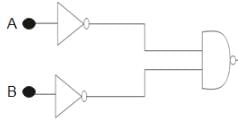
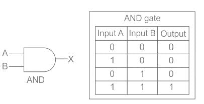
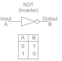
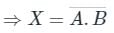
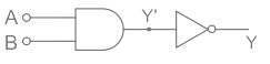
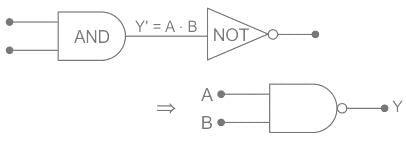
What will be the output of the combination of AND gate and NOT gate if the inputs are A and B?
Detailed Solution: Question 8
Detailed Solution: Question 9
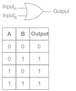
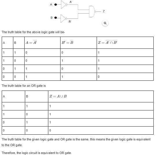
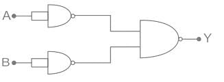
Identify the logic gate carried out by the following circuit.
Detailed Solution: Question 10
Detailed Solution: Question 11
Detailed Solution: Question 12
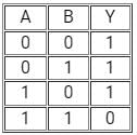
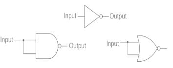
Identify the logic operation carried out by the following circuit.
Detailed Solution: Question 13
Detailed Solution: Question 14

Detailed Solution: Question 15
113 videos|91 docs|58 tests |