Mechanical Engineering Exam  >  Mechanical Engineering Tests  >  Mechanical Engineering SSC JE (Technical)  >  Test: Machine Design - 2 - Mechanical Engineering MCQ

Test: Machine Design - 2 - Mechanical Engineering MCQ


Test Description

25 Questions MCQ Test Mechanical Engineering SSC JE (Technical) - Test: Machine Design - 2

Test: Machine Design - 2 for Mechanical Engineering 2024 is part of Mechanical Engineering SSC JE (Technical) preparation. The Test: Machine Design - 2 questions and answers have been prepared according to the Mechanical Engineering exam syllabus.The Test: Machine Design - 2 MCQs are made for Mechanical Engineering 2024 Exam. Find important definitions, questions, notes, meanings, examples, exercises, MCQs and online tests for Test: Machine Design - 2 below.
Solutions of Test: Machine Design - 2 questions in English are available as part of our Mechanical Engineering SSC JE (Technical) for Mechanical Engineering & Test: Machine Design - 2 solutions in Hindi for Mechanical Engineering SSC JE (Technical) course. Download more important topics, notes, lectures and mock test series for Mechanical Engineering Exam by signing up for free. Attempt Test: Machine Design - 2 | 25 questions in 50 minutes | Mock test for Mechanical Engineering preparation | Free important questions MCQ to study Mechanical Engineering SSC JE (Technical) for Mechanical Engineering Exam | Download free PDF with solutions
Test: Machine Design - 2 - Question 1

The design calculations for members subject to fluctuating loads with the same factor of safety yield the most conservative estimates when using

Detailed Solution for Test: Machine Design - 2 - Question 1

Correct Answer :- C

Explanation : The soderberg line is a more conservative failure criterion and there is no need to consider even yielding in this case.

Test: Machine Design - 2 - Question 2

If a shaft made from ductile material is subjected to combined bending and twisting moment, calculations based on which one of the following failure theories will give the most conservative value?

Detailed Solution for Test: Machine Design - 2 - Question 2

Correct Answer :- b

Explanation : The concept of equivalent torsional moment is used in the design of shafts on the basis of maximum shear stress theory of failure.  The concept of equivalent bending moment is used in the design of shafts on the basis of maximum principal stress theory of failure

1 Crore+ students have signed up on EduRev. Have you? Download the App
Test: Machine Design - 2 - Question 3

If the size of a standard specimen for a fatigue testing machine is increased, the endurance limit for the material will

Detailed Solution for Test: Machine Design - 2 - Question 3
Explanation:
When the size of a standard specimen for a fatigue testing machine is increased, the endurance limit for the material will decrease. This is due to the following reasons:
1. Size effect:
- When the size of the specimen increases, the stress concentration at notches or defects decreases, resulting in a reduced stress intensity factor.
- The stress intensity factor is a measure of the severity of the stress distribution at the crack tip.
- A smaller stress intensity factor leads to a higher endurance limit, indicating that the material can withstand a higher number of cycles before failure.
- Conversely, a larger stress intensity factor, caused by the increased size of the specimen, will result in a lower endurance limit.
2. Stress redistribution:
- When the size of the specimen increases, the stress distribution within the material changes.
- The stress is redistributed, leading to higher levels of stress at certain regions of the specimen.
- These regions of higher stress can lead to crack initiation and propagation, reducing the endurance limit of the material.
Conclusion:
Therefore, when the size of a standard specimen for a fatigue testing machine is increased, the endurance limit for the material will decrease. Thus, the correct answer is option C: decreases.
Test: Machine Design - 2 - Question 4

Stress concentration in a machine component of ductile materials not so harmful as it is in brittle material because

Detailed Solution for Test: Machine Design - 2 - Question 4
Why stress concentration in a machine component of ductile materials is not as harmful as in brittle materials:

A: In Ductile material local yielding may distribute stress concentration:


  • When stress is applied to a ductile material, it undergoes plastic deformation rather than fracturing.

  • This plastic deformation allows the material to redistribute the stress concentration over a larger area, reducing the risk of failure.

  • The localized yielding absorbs some of the stress, preventing it from being concentrated in one specific area.


B: Ductile material have large Young's modulus:


  • Young's modulus is a measure of a material's stiffness or resistance to deformation.

  • Ductile materials generally have a higher Young's modulus compared to brittle materials.

  • This means that ductile materials can withstand higher stress without experiencing excessive deformation or failure.


C: Poisson's ratio is larger in ductile materials:


  • Poisson's ratio is a measure of the lateral contraction of a material when it is subjected to axial tension or compression.

  • Ductile materials typically have a larger Poisson's ratio compared to brittle materials.

  • This allows ductile materials to expand laterally under stress, reducing the concentration of stress in a localized region.


D: Modulus of rigidity is larger in ductile material:


  • The modulus of rigidity, also known as shear modulus, measures a material's resistance to shear deformation.

  • Ductile materials generally have a larger modulus of rigidity compared to brittle materials.

  • This higher modulus of rigidity enables ductile materials to withstand shear stress and deformation without catastrophic failure.


In conclusion, stress concentration in a machine component made of ductile materials is not as harmful as in brittle materials due to the ability of ductile materials to undergo plastic deformation, their higher Young's modulus, larger Poisson's ratio, and larger modulus of rigidity. These factors help distribute stress and prevent it from being concentrated in a small area, reducing the risk of failure.

Test: Machine Design - 2 - Question 5

A solid circular shaft is subjected to pure torsion. The ratio of maximum shear stress to maximum normal stress at any point would be

Detailed Solution for Test: Machine Design - 2 - Question 5
Explanation:
To determine the ratio of maximum shear stress to maximum normal stress in a circular shaft subjected to pure torsion, we can use the equations for shear stress and normal stress.
The maximum shear stress in a circular shaft is given by the equation:
τmax = (T * r) / J
where τmax is the maximum shear stress, T is the applied torque, r is the radius of the shaft, and J is the polar moment of inertia of the shaft.
The maximum normal stress in a circular shaft is given by the equation:
σmax = (T * r) / Z
where σmax is the maximum normal stress, T is the applied torque, r is the radius of the shaft, and Z is the section modulus of the shaft.
Now, let's compare the ratio of maximum shear stress to maximum normal stress:
τmax / σmax = (T * r) / J / (T * r) / Z
= Z / J
Key Points:
- The ratio of maximum shear stress to maximum normal stress is equal to the ratio of the section modulus to the polar moment of inertia.
- For a solid circular shaft, the section modulus (Z) is equal to the polar moment of inertia (J).
- Therefore, the ratio of maximum shear stress to maximum normal stress is 1:1.
Answer:
The ratio of maximum shear stress to maximum normal stress at any point in a solid circular shaft subjected to pure torsion is 1:1. (Option A)
Test: Machine Design - 2 - Question 6

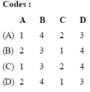
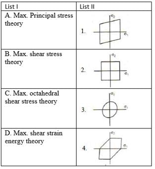
Match List-I (Failure theories) with List-II (Figures representing boundaries of these theories) and select the correct answer using the code given below the lists:
Test: Machine Design - 2 - Question 7

The maximum distortion energy theory of failure is suitable to predict the failure of which one of the following types of materials ?

Test: Machine Design - 2 - Question 8

Which one of the following figures represents the maximum shear stress theory of TRESCA criterion ?

Detailed Solution for Test: Machine Design - 2 - Question 8
Explanation:
The maximum shear stress theory of Tresca criterion states that failure occurs when the maximum shear stress in a material exceeds a certain limit. This criterion is also known as the maximum distortion energy theory or the shear stress theory.
To determine which figure represents the maximum shear stress theory of Tresca criterion, we need to analyze the stress distribution in each figure and identify the maximum shear stress regions.
Let's examine each figure:
Figure A:
- In this figure, the stress distribution is uniform along the cross-section, and there are no concentrated areas of stress. Therefore, it does not represent the maximum shear stress theory of Tresca criterion.
Figure B:
- In this figure, there are concentrated areas of stress at the corners of the cross-section. These areas experience the maximum shear stress, indicating that this figure represents the maximum shear stress theory of Tresca criterion.
Figure C:
- In this figure, there are concentrated areas of stress at the sides of the cross-section. These areas experience the maximum shear stress, indicating that this figure represents the maximum shear stress theory of Tresca criterion.
Figure D:
- In this figure, the stress distribution is uniform along the cross-section, and there are no concentrated areas of stress. Therefore, it does not represent the maximum shear stress theory of Tresca criterion.
Therefore, the correct answer is C: Figure C represents the maximum shear stress theory of Tresca criterion.
Test: Machine Design - 2 - Question 9

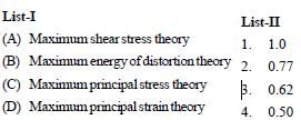
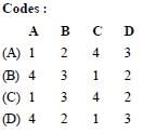
Match List-I (Theory of Failure) with List-II (Predicted Ratio of Shear Stress to Direct Stress at yield Condition for Steel Specimen) select the correct answer using the code given below the lists:
Test: Machine Design - 2 - Question 10

Disruptive strength is the maximum strength of a metal, when

Detailed Solution for Test: Machine Design - 2 - Question 10
Disruptive Strength of a Metal
The disruptive strength of a metal refers to its maximum strength under certain conditions. Let's discuss each option and determine which one is correct.
A: Subjected to 3 principal tensile stresses at right angles to one another and of equal magnitude
When a metal is subjected to three principal tensile stresses at right angles to one another and of equal magnitude, the disruptive strength is measured. This means that the metal is being pulled apart in three different directions simultaneously.
B: Loaded in tension
When a metal is loaded in tension, it means that a force is being applied to stretch the metal. This is a common testing method to determine the strength of a metal.
C: Loaded in compression
When a metal is loaded in compression, it means that a force is being applied to compress or squeeze the metal. This is another common testing method to determine the strength of a metal.
D: Loaded in shear
When a metal is loaded in shear, it means that a force is being applied parallel to the surface of the metal, causing it to slide or deform. Shear strength is another important property of a metal.
Answer: A: Subjected to 3 principal tensile stresses at right angles to one another and of equal magnitude
Based on the given options, the correct answer is A. The disruptive strength of a metal is measured when it is subjected to three principal tensile stresses at right angles to one another and of equal magnitude. This testing method provides valuable information about the maximum strength of the metal under complex loading conditions.
Test: Machine Design - 2 - Question 11

Who postulated the maximum distortion energy theory?

Detailed Solution for Test: Machine Design - 2 - Question 11
Answer:
The maximum distortion energy theory, also known as the von Mises-Hencky theory or the octahedral shear stress theory, was postulated by Richard von Mises and Paul Hencky.
Explanation:
The maximum distortion energy theory is a criterion used to predict the failure of ductile materials under complex loading conditions. It is based on the assumption that failure occurs when the distortion energy per unit volume reaches a critical value.
Key points to note about the individuals who postulated the maximum distortion energy theory:
1. Tresca:
- Tresca, also known as Henri Édouard Tresca, was a French engineer and physicist.
- He is known for his work in the field of material science and the study of the behavior of materials under stress.
- Tresca proposed the Tresca yield criterion, which is a criterion for predicting the yield of ductile materials under uniaxial stress.
2. Rankine:
- William John Macquorn Rankine was a Scottish engineer and physicist.
- He made significant contributions to the fields of thermodynamics and engineering.
- Rankine formulated the Rankine-Hencky theory, which is a theory that relates the strain energy of a material to its elastic properties.
3. St. Venant:
- Barré Charles Paul Édouard de Saint-Venant, commonly referred to as Saint-Venant, was a French engineer and mathematician.
- He is known for his work on the theory of elasticity and the study of stress and strain in materials.
- Saint-Venant developed the Saint-Venant's principle, which is a principle used to approximate the stress and strain distribution near the ends of a loaded structural member.
4. Mises-Hencky:
- Richard von Mises, an Austrian-American mathematician, and Paul Hencky, a Czech mathematician, independently formulated the maximum distortion energy theory.
- The theory, also known as the von Mises-Hencky theory or the octahedral shear stress theory, is widely used in engineering to predict the failure of ductile materials.
In conclusion, the correct answer is D: Mises-Hencky.
Test: Machine Design - 2 - Question 12

A rotating shaft carrying a unidirectional transverse load is subjected to :

Test: Machine Design - 2 - Question 13

In the design of connecting rod small end bearing, the value of permissible bearing pressure to be used is :

Test: Machine Design - 2 - Question 14

For bolts of uniform strength, the shank diameter is made equal to

Detailed Solution for Test: Machine Design - 2 - Question 14
Explanation:
To understand why the shank diameter of bolts of uniform strength is made equal to the minor diameter of threads, let's break it down into key points:
1. Bolts of Uniform Strength: Bolts are used to join two or more parts together. The shank of the bolt is the cylindrical part that provides the majority of the strength.
2. Threaded Bolts: Bolts have threads on their shank, which allow them to be screwed into a corresponding threaded hole or nut.
3. Different Thread Diameters: Threads have three main diameters: major diameter, minor diameter, and pitch diameter.
4. Major Diameter: The major diameter is the largest diameter of the thread profile. It represents the outermost points of the threads.
5. Minor Diameter: The minor diameter is the smallest diameter of the thread profile. It represents the innermost points of the threads.
6. Pitch Diameter: The pitch diameter is the effective diameter of the thread, where the threads perfectly mesh with the corresponding threaded hole or nut.
7. Uniform Strength: Bolts of uniform strength are designed to have the same strength throughout their length, including the shank and the threaded portion.
8. Equal Shank and Minor Diameter: To achieve uniform strength, the shank diameter of the bolt is made equal to the minor diameter of the threads. This ensures that the shank and the threaded portion have the same strength.
9. Load Distribution: Making the shank diameter equal to the minor diameter helps in distributing the load evenly across the bolt. It prevents stress concentration at the transition between the shank and the threaded portion.
In conclusion, for bolts of uniform strength, the shank diameter is made equal to the minor diameter of the threads. This design ensures equal strength throughout the bolt and helps in distributing the load evenly.
Test: Machine Design - 2 - Question 15

A butt welded joint, subjected to tensile force P is shown in the given figure, l = length of the weld (in mm) h = throat of the butt weld (in mm) and H is the total height of weld including reinforcement. The average tensile stress st in

Test: Machine Design - 2 - Question 16

In the welded joint shown in the given figure if the weld at B has thicker fillets than at A then load carrying capacity P0 of the joint will

Test: Machine Design - 2 - Question 17

When a nut is tightened by placing a washer below it the bolt will be subjected to

Detailed Solution for Test: Machine Design - 2 - Question 17
The answer is A: tensile stress.
When a nut is tightened by placing a washer below it, the bolt will be subjected to tensile stress. This means that the bolt will experience a stretching force along its length. Here is a detailed explanation:
1. Tensile stress:
- Tensile stress occurs when a force is applied to an object, causing it to stretch or elongate.
- In this case, when the nut is tightened, the washer applies a compressive force on the bolt, which in turn causes the bolt to stretch.
- The bolt is subjected to tensile stress because it experiences a force that tries to pull it apart along its length.
2. Compression stress:
- Compression stress occurs when a force is applied to an object, causing it to compress or shorten.
- In this scenario, the washer applies a compressive force on the bolt, but it does not cause the bolt to shorten or compress. Instead, it causes the bolt to stretch.
3. Shear stress:
- Shear stress occurs when a force is applied parallel to the surface of an object, causing it to deform or slide.
- In this case, the washer does not exert a force parallel to the surface of the bolt, so there is no shear stress involved.
4. None of these:
- The correct answer is not "none of these" because the bolt is indeed subjected to a type of stress, which is tensile stress.
In conclusion, when a nut is tightened by placing a washer below it, the bolt will be subjected to tensile stress as it experiences a force that tries to pull it apart along its length.
Test: Machine Design - 2 - Question 18

The rivet head used for boiler plate riveting is usually

Detailed Solution for Test: Machine Design - 2 - Question 18
Answer:
The rivet head used for boiler plate riveting is usually a snap head. Here is a detailed explanation:
What is boiler plate riveting?
Boiler plate riveting is a method used to fasten two or more metal plates together by using rivets. Rivets are cylindrical metal fasteners that are inserted through holes in the plates and then hammered or compressed to create a permanent connection.
The types of rivet heads:
There are various types of rivet heads available, but the most commonly used head for boiler plate riveting is the snap head. However, it's important to note that different types of rivet heads have different applications and are chosen based on the specific requirements of the project.
Why is the snap head used for boiler plate riveting?
The snap head is specifically designed for boiler plate riveting due to its unique features and benefits. Here are some reasons why the snap head is preferred:
1. Increased strength: The snap head has a large, flat surface area that provides a strong grip on the plates, ensuring a secure connection.
2. Flush appearance: The snap head sits flush with the surface of the plates once it is properly installed, creating a smooth and aesthetically pleasing finish.
3. Easy installation: The snap head is easy to install using a riveting hammer or a riveting machine, making it a convenient choice for boiler plate riveting.
4. Good load distribution: The shape of the snap head allows for even load distribution across the rivet, reducing the risk of stress concentration and potential failure.
Conclusion:
In summary, the snap head is the preferred rivet head for boiler plate riveting due to its strength, flush appearance, ease of installation, and good load distribution. It is important to choose the appropriate rivet head based on the specific requirements of the project to ensure a reliable and durable connection between the metal plates.
Test: Machine Design - 2 - Question 19

The piston rod and the crosshead in a steam engine are usually connected by means of

Detailed Solution for Test: Machine Design - 2 - Question 19
Introduction:
In a steam engine, the piston rod and the crosshead are crucial components that play a significant role in converting the linear motion of the piston into the rotational motion of the crankshaft. The connection between the piston rod and the crosshead needs to be strong and flexible to handle the reciprocating motion effectively.
Connection between the piston rod and the crosshead:
The piston rod and the crosshead in a steam engine are typically connected by means of a cotter joint.
Explanation:
A cotter joint is a type of mechanical joint that provides a strong and reliable connection between two rods or bars. It consists of a tapered slot in the end of one rod and a corresponding wedge-shaped cotter that fits into the slot. The cotter is inserted through a hole in the second rod and secured with a nut. This arrangement allows for a tight and secure connection between the piston rod and the crosshead.
Advantages of a cotter joint:
- High strength: The cotter joint provides a strong connection, capable of withstanding the reciprocating forces in a steam engine.
- Easy assembly and disassembly: The cotter joint can be easily assembled and disassembled, making maintenance and repairs more convenient.
- Adjustable fit: The tapered slot and cotter allow for adjustment, ensuring a tight fit between the piston rod and the crosshead.
Conclusion:
In conclusion, the piston rod and the crosshead in a steam engine are usually connected by means of a cotter joint. This type of joint offers a secure and flexible connection, allowing for the efficient conversion of linear motion to rotational motion in the engine.
Test: Machine Design - 2 - Question 20

For longitudinal joint in boiler, the type of joint used is

Detailed Solution for Test: Machine Design - 2 - Question 20
Longitudinal Joint in a Boiler
The type of joint used for the longitudinal joint in a boiler is a butt joint with a double cover plate. This joint is commonly used in boiler construction due to its strength and reliability.
Reasons for Using a Butt Joint with Double Cover Plate:
- Strength: The double cover plate provides added strength to the joint, ensuring that it can withstand the high pressure and stress conditions experienced in boiler operations.
- Leak Prevention: The double cover plate helps to prevent leaks by providing an additional layer of protection against the escape of steam or water.
- Uniform Distribution of Stress: The double cover plate helps to distribute stress more uniformly along the joint, reducing the likelihood of localized weak points.
- Weldability: Butt joints are relatively easy to weld, making them a preferred choice in boiler construction.
- Cost-effectiveness: The use of a butt joint with a double cover plate offers a cost-effective solution while maintaining the necessary strength and reliability.
In summary, the type of joint used for the longitudinal joint in a boiler is a butt joint with a double cover plate. This joint provides the required strength, leak prevention, and uniform stress distribution needed for efficient and safe boiler operation.
Test: Machine Design - 2 - Question 21

For the bracket bolted as shown in the above figure, the bolts will develop

Test: Machine Design - 2 - Question 22

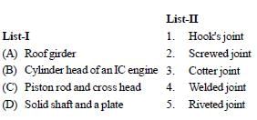
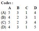
Match List-I (Applications) with List-II (Joints) and select the correct answer using the code given below the lists:
Test: Machine Design - 2 - Question 23

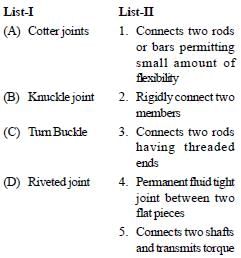
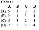
Match List-I (Type of joints) List-II (Mode of connecting member) and select the correct answer using the code given below the lists:
Test: Machine Design - 2 - Question 24

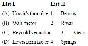
Match List-I with List-II and select the correct answer using the code given below the lists:

Test: Machine Design - 2 - Question 25

 Which of the following property is affected by heat treatment?

Detailed Solution for Test: Machine Design - 2 - Question 25

Heat treatment involves changes in the micro structure and hence all the internal properties are effected.

5 videos|103 docs|59 tests
Information about Test: Machine Design - 2 Page
In this test you can find the Exam questions for Test: Machine Design - 2 solved & explained in the simplest way possible. Besides giving Questions and answers for Test: Machine Design - 2, EduRev gives you an ample number of Online tests for practice

Top Courses for Mechanical Engineering

Download as PDF

Top Courses for Mechanical Engineering