1 Crore+ students have signed up on EduRev. Have you? Download the App |
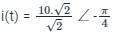
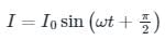
The voltage applied to a circuit is 100 √2 cos (100πt) volts and the circuit draws a current of 10 √2 sin (100πt + π / 4) amperes. Taking the voltage as the reference phasor, the phasor representation of the current in amperes is
Given that
V(t) = 100√2 cos (100πt),
i(t) = 10√2 sin(100π + π/4).
To consider voltage as a reference phasor, The First step would be to make Cosine as Sine by adding 90º to its phase.
V(t) = 100√2 cos (100πt)
= 100√2 sin (100πt + π/2)
i(t) = 10√2 sin(100π + π/4)
Phasor diagram for above two equations can drown as below.
As you can see by considering voltage as reference current leg behind by 45º.
So RMS value of current in phasor form is
=
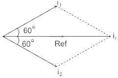
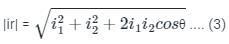
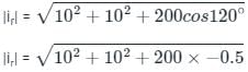
Three currents i1, i2, and i3 meet at a node. if i1 = 10 sin (400t + 60°) A, and i2 = 10sin (400t - 60°) A then i3 =
Kirchhoff’s Current Law (KCL): It states that the algebraic sum of currents entering a node or closed boundary is zero.
Mathematically, KCL implies that
Where N is the number of branches connected to the node
And in is the nth current entering or leaving the node.
By this law current entering a node may be regarded as positive and current leaving a node may be regarded as negative or vice-versa.
Hence, the sum of currents entering a node is equal to the sum of the currents leaving the node.
Calculation:
Given that, three currents i1, i2, and i3 meet at a node,
From the above concept,
i1,+ i2, + i3 = 0
or, i3 = - (i1 + i2)
Since the current is given in phasor form, hence the addition of current i1 and i2 can be done by using the parallelogram method,
We have,
i1 = 10 sin (400t + 60°) A .... (1)
i2 = 10sin (400t - 60°) A .... (2)
The phasor diagram can be drawn as,
By using the parallelogram method,
Where, it is the resultant current
We have, θ = (60° + 60°) = 120°
From equation (1), (2) & (3),
= 10
Since i1 & i2 has the same phase angle as well as the magnitude,
∴ ir = 10sin 400t A
Since the sum of all current is zero, hence,
i3 = - ir = - 10sin 400t A
Types of loads and Phasor Diagrams:
Pure Inductor load:
Pure capacitor:
RL load:
RLC Load:
Case I
RLC load with inductive reactance more than the capacitive reactance
Where
VL = Inductor voltage
VC = Capacitor voltage
I = Current
V = Supply voltage
VR = Resistor Voltage
Case II
RLC load with inductive reactance lesser than the capacitive reactance
So If we observe the phasor diagram between V and I in all cases, RL load or RLC with inductive reactance more than the capacitive reactance (Case II) matches the given phasor.
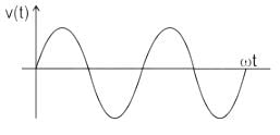
In phasor representation of an alternating quantity, the sinusoidally varying alternating quantity can be represented graphically by:
Concept:
A phasor is a vector representation of a sinusoidal function that has both a magnitude and a phase angle.
Representations:
Rectangular form: z = x + jy
Polar form: z = r ∠ ϕ
Exponential form: z = z ejϕ
Comparison:
Time Domain: V(t) = Vm cos (ωt + ϕ)
It represents the voltage as a function of time as shown:
Phasor Domain: V = Vm ∠ ϕ
It gives the magnitude and phase and can be represented as:
Where,
Vm is the magnitude of the voltage function
ϕ is the phase angle of the voltage function
Note:
Power factor = cos ϕ
In the phasor representation of an alternating quantity, the sinusoidally varying alternating quantity can be represented graphically by a straight line with an arrow.
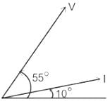
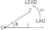
The current in the inductive circuit is 10 A and power factor is 0.866. The phasor representation of current is:
Given-
Im = 10 A,
Power factor = 0.866 lagging (∵ inductive circuit)
∴ cosϕ = cos-1(0.866)
∴ ϕ = -30° (∵ lagging power factor)
So that phasor representation of current is given by
I = 10 ∠-30° A
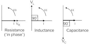
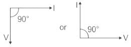
For a pure resistance supplied through a sinusoidal voltage, the phase difference between the voltage and current phasors will be _______.
Resistance:
Inductance:
Capacitance:
Hence the correct option for angle between the current and voltage in pure resistive circuit is zero or 0°.
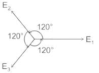
Three different coils produce a same EMF of 100 V when moved at a constant speed in the magnetic field. The induced EMF in the first coil lags to the induced EMF in the second coil and leads to the induced EMF in the third coil. So, what will be the resultant EMF in the series combination of the three coils?
Concept:
Coils induce EMF if moved with constant velocity in the magnetic field in accordance with Faraday's law of electromagnetic induction, and this EMF is also called Motional EMF. This is a basic law of electromagnetism.
Sum of 3 equal phasors at 0°,120°, -120° apart is zero.
Calculations :
Consider, E1 = 100∠0 V, E2 = 100∠120 V, E3 = 100∠-120 V
Resultant EMF, ER = E1 + E2 + E3
ER = 100∠0 + 100∠120 + 100∠-120
ER = 100ej0 + 100ej120+100e−j120
=100[ej0+ej120+e−j120]
=100[1+2cos(120)]
= 0
A phasor
1. may be a scalar or a vector
2. is a time-dependent quantity
3. is a complex quantity
Which of the above statements are correct?
Phasor diagrams are a graphical way of representing the magnitude and directional relationship between two or more alternating quantities.
Basically, a rotating vector called a Phasor is a scaled line whose length represents an AC quantity that has both magnitude and direction which is frozen at some point in time.
Characteristics:
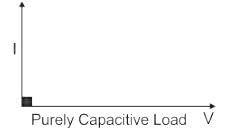
The phase difference between current and voltage in a pure capacitive circuit is:
When the Alternating emf is running in the circuit is
e = e0 sin ωt
Current in the inductive circuit is –
Hence
the Phase difference between current and voltage in pure capacitive circuit is 90° or π/2.
The non linear magnetization curve of a practical transformer will introduce _________
If the magnetization is non linear in nature then it will cause a saturation in the core and harmonics will be introduced to cause humming sounds.
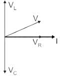
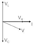
Which of the following equation correctly represents the exact phasor diagram of transformer?
According to the primary and secondary equivalent circuits of a transformer equation stated in option 1 correctly suits with the kirchoff’s voltage law for primary side of a transformer, similarly equation for secondary side can also be written down.
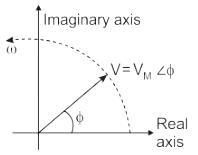
If the phasors are drawn to represent the maximum values instead of the rms values, what would happen to the phase angle between quantities?
When phasors are drawn representing the maximum values instead of the rms value, the shape of the diagram remains unaltered and hence the phase angle remains the same.
Ammeters and voltmeters are calibrated to read the rms value, hence the phasors are drawn representing the rms values.
We know that the rms value is 1/√2 times the maximum value, hence the rms value is 0.707 times the maximum value.
Graph of Ef vs Ff is the open circuit characteristic of the machine.
23 videos|63 docs|61 tests
|
23 videos|63 docs|61 tests
|