Test: Power Systems- 7 - Electrical Engineering (EE) MCQ
10 Questions MCQ Test - Test: Power Systems- 7

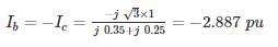
Determine the fault current in a system following a double line to ground short circuit at the terminals of a star connected synchronous generator operating initially on an open circuit voltage of 1.0 pu. The positive, negative and zero sequences reactance of the generator are, respectively j 0.35, j 0.25 and j 0.20 and the star point is isolated from ground.
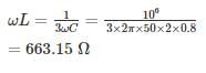
A 50 Hz overhead Line has Line to each capacitance of 2 μF. It is decided to use an earth fault neutralizer. The reactance to neutralizer. The reactance to neutralize the capacitance of 80% of the length of the line is – (in ohms)

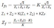
A positive, negative and zero sequence impedance of 3ϕ generator are Z1, Z2 and Z0 respectively. For a line to line fault with fault impedance ZF, the fault current is IF1 = KIF. Where IF is the fault current with zero fault impedance. The relation between ZF and K is
A three phase 15 MVA, 13 kV alternator has an initial reactance of 5%. The series reactor needed to restrict the short circuit current of the alternator to 10 times of full load current is _____ (in Ω).

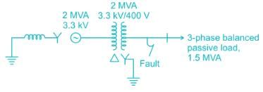
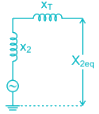
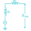
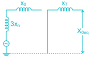
A 2 MVA, 3.3 kV, three-phase generator as the following reactance’s on its own base:
+ve sequence reactance, x1 = j0.10 p.u.
-ve sequence reactance, x2 = j0.10 p.u.
Zero sequence reactance, x0 = j0.05 p.u.
Reactance from neutral to ground, xn = j0.05 p.u.
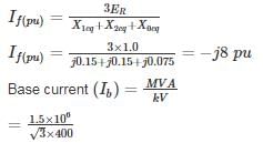
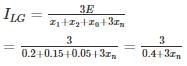
The generator supplies a 3-phase, 1.5 MVA balanced passive load through a 3-phase, 2.0 MVA, 3.3 kV/400 V, delta-star transform with leakage reactance of 10%, as shown in the figure. A single-line-to-ground fault takes place at the low voltage side of the transformer. The current flowing from the transformer to the fault is (Assume base MVA is 1.5 MVA)

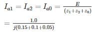
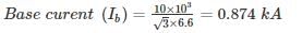
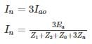
A 10 MVA, 6.6 kV generator has percentage reactances to positive, negative and zero sequence currents of 15%, 10%, and 5% respectively and it's neutral is solidly grounded. The generator is unloaded and excited to its rated voltage. The fault current (in kA) will be when a single line to ground fault develops on phase a of the generator. The phase sequence is ABC.
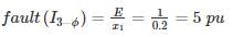
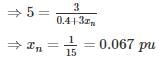
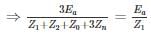
For an unloaded generator, at rated voltage, the magnitude of fault current for a three-phase fault is the same as LG fault. The reactances of the generator are
x1 = 0.2 pu, x2 = 0.15 pu, x0 = 0.05 pu
The value of the neutral grounding reactance is ______ (in pu)
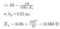
The severity of line to ground and three phase faults is to be same. If the terminal voltage is 1.0 pu, Z1 = Z2 = j 0.1 pu and Z0 = j 0.05 pu for an alternator, then the required inductive reactance for neutral grounding is

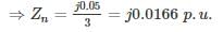
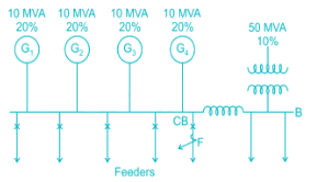
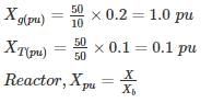
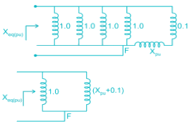
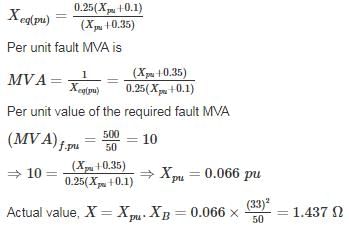
The 33 kV busbars of a station are in two sections A and B separated by a reactor. Section A is fed from four 10 MVA generators each having a reactance of 20% section B is fed from the grid through a 50 MVA transformer of 10% reactance. The circuit breakers have each a rupturing capacity of 500 MVA. Find the reactance (in Ω) of the reactor to prevent the circuit breakers from being overloaded, if a symmetrical three-phase fault occurs on an outgoing feeder connected for it. (Take base voltage of 33 KV and base MVA of 50).
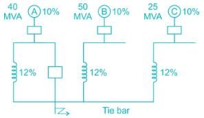
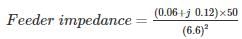
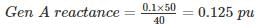
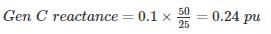
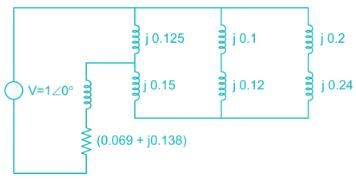
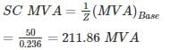
Three 6.6 kV generators A, B and C each of 10% leakage reactance and MVA ratings 40, 50 and 25, respectively are interconnected electrically as shown in the figure, by a tie bar through current limiting reactors, each of 12% reactance based upon the rating of the machine to which it is connected. A three-phase feeder is supplied from the bus bar of generator A at a line voltage of 6.6 kV. The feeder has a resistance of 0.06 Ω/phase and an indicative reactance of 0.12 Ω/phase. Estimate the maximum MVA that can be fed into asymmetrical short circuit at the far end of the feeder.
Important Questions for Power Systems- 7
Power Systems- 7 MCQs with Answers
Online Tests for Power Systems- 7
|
© EduRev
|
Education Revolution
|


|


