Test: Pulse Amplitude Modulation (PAM) - Electronics and Communication Engineering (ECE) MCQ
10 Questions MCQ Test GATE ECE (Electronics) Mock Test Series 2025 - Test: Pulse Amplitude Modulation (PAM)

| 1 Crore+ students have signed up on EduRev. Have you? Download the App |
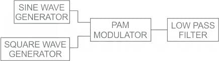
Which filter is used to detect the PAM signal?
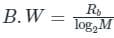
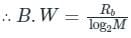
A speech signal is sampled a rate of 20% above the Nyquist rate. The signal has a bandwidth of 10 kHz. The sample is quantized into 1024 levels and then transmitted through 8-level PAM over an AWGN baseband channel. The bandwidth required for transmission is ______


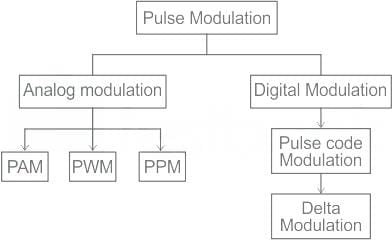
Which of the following Pulse time Modulation does not exist in practice?


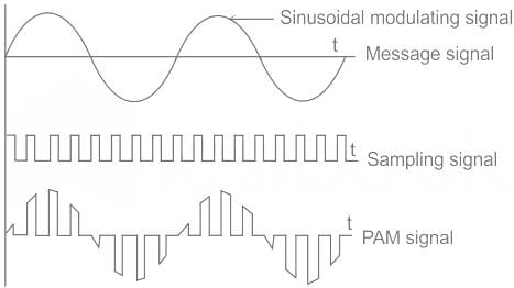
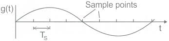
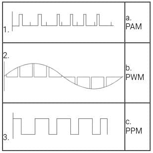
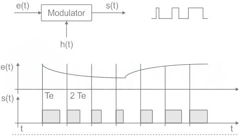
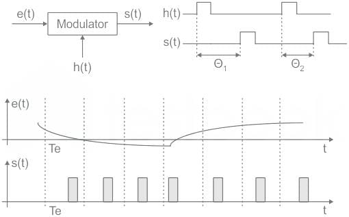
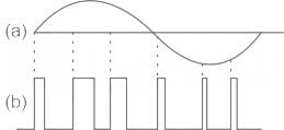
Study the given input signal and match the columns.

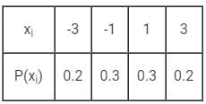
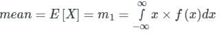
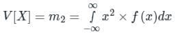
A PAM source generates four symbols 3 V, 1 V, -1 V and -3 V with probability of p(3) = p(-3) = 0.2 and p(1) = p(-1) = 0.3 respectively. The variance for the source will be

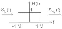
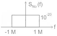
Consider a baseband binary PAM receiver shown below. The additive channel noise n(t) is white with power spectral density SN(f) = N0/2 = 10-20 W/Hz. The low-pass filter is ideal with unity gain and cutoff frequency 1 MHz. Let Yt, represent the random variable y(t1)
Yt = Ns if transmitted bit bk = 0
YK = a + Nk if transmitted bit bk = 1
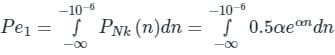
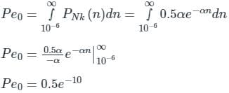
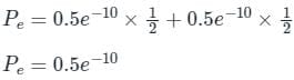
where Nk represents the noise sample value. The noise sample has a probability density function, PN (n) = 0.5αe (This has mean zero and variance 2/α2), Assume transmitted bits lo be equiprobable and threshold z is set to a/2 = 10-6 V
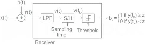
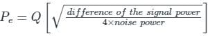
‘The probability of bit error is
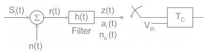
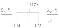

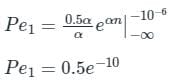
Consider a baseband binary PAM receiver shown below. The additive channel noise n(t) is white with power spectral density SN(f) = N0/2 = 10-20 W/Hz. The low-pass filter is ideal with unity gain and cutoff frequency 1 MHz. Let Yt, represent the random variable y(t1)
Yt = Ns if transmitted bit bk = 0
YK = a + Nk if transmitted bit bk = 1
where Nk represents the noise sample value. The noise sample has a probability density function, PN (n) = 0.5αe (This has mean zero and variance 2/α2), Assume transmitted bits lo be equiprobable and threshold z is set to a/2 = 10-6 V

Q. The value of the parameter α (in V-1) is
Which of the following is NOT an advantage of Pulse Duration Modulation (PDM) recording?
|
25 docs|263 tests
|
|
25 docs|263 tests
|
Top Courses for Electronics and Communication Engineering (ECE)


Important Questions for Pulse Amplitude Modulation (PAM)
Pulse Amplitude Modulation (PAM) MCQs with Answers
Online Tests for Pulse Amplitude Modulation (PAM) GATE ECE (Electronics) Mock Test Series 2025
|
© EduRev
|
Education Revolution
|


Follow Us
|


