1 Crore+ students have signed up on EduRev. Have you? |
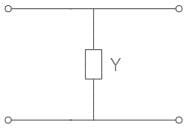
Shunt capacitance is neglected in the analysis of which transmission lines?
Types of transmission lines:
Depending upon the length of the line, it is divided into three types:
Shunt capacitance is neglected in the analysis of short transmission lines. This is because:
The capacitive reactance is given by:
Since the value of length (l) is small in the short transmission lines, therefore the reactance becomes very high.
High reactance means an open circuit, hence effect of capacitance is neglected in the short transmission lines.
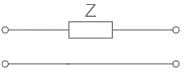
A short transmission line has impedance value Z. The values of A, D, B and C of the short transmission line are _______, respectively
Concept:
The ABCD parameters of the above circuit diagram are
When the networks are connected in cascade, their ABCD parameters will get multiplied.
Calculation:
A short transmission line can be modelled as a series impedance
z = R + jωL
The ABCD constants of this series impedance are
A = D = 1, B = z, C = 0
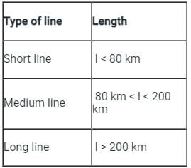
When the length of an overhead transmission line is less than 80 km with an operating voltage upto 20 kV, it is considered to be a/an ___________.
Classification of Overhead Transmission Lines:
Depending upon the manner in which capacitance is taken into account, the overhead transmission lines are classified as:
Short transmission lines:
When the length of an overhead transmission line is up to about 50 km to 80 km and the line voltage is comparatively low (< 20 kV), it is usually considered as a short transmission line. Due to smaller lengths and lower voltage, the capacitance effects are small and hence can be neglected. Therefore, while studying the performance of a short transmission line, only the resistance and inductance of the line are taken into account.
Medium transmission lines:
When the length of an overhead transmission line is about 80-150 km and the line voltage is moderately high (>20 kV < 100 kV), it is considered a medium transmission line. Due to the sufficient length and voltage of the line, the capacitance effects are taken into account. For purposes of calculations, the distributed capacitance of the line is divided and lumped in the form of condensers shunted across the line at one or more points.
Long transmission lines:
When the length of an overhead transmission line is more than 150 km and line voltage is very high (> 100 kV), it is considered a long transmission line. For the treatment of such a line, the line constants are considered uniformly distributed over the whole length of the line and rigorous methods are employed for the solution
The insulation strength of an EHV transmission line is mainly governed by
Switching surges are the governing factor in the design of insulation for EHV and UHV transmission lines.
Origins of switching overvoltage:
The effective length of a short transmission line is less than __________.
Short transmission lines:
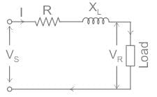
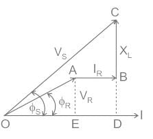
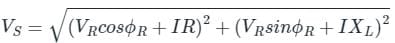
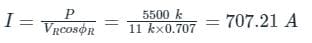
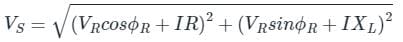
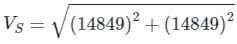
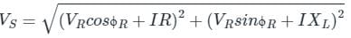
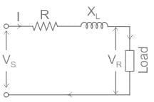
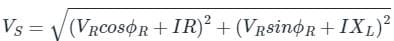
A single phase overhead transmission line delivers a power of 5500 kW to a load at 11 kV. The receiving end voltage leads the current by 45°. The resistance and the inductive reactance of the transmission line are 10 Ω and 10 Ω respectively. The sending end voltages is
Concept:
Short Transmission Line:
When the length of the overhead transmission line is up to about 50 km and the line voltage is comparatively up to 20 kV.
Due to smaller lengths and lower voltage, the capacitance effect is small and may be neglected.
Considered a short transmission line of resistance R and Reactance XL over a length.
Vs is the sending end voltage
VR is the receiving end voltage
I is the load current.
cos ϕR is receiving end power factor
and, cos ϕs is sending end power factor
The phasor diagram of the system can be drawn by taking load current as a reference,
From the phasor,
(OC)2 = (OD)2 + (DC)2
(OC)2 = (OE + ED)2 + (DB + BC)2
V2S = (VR cos ϕR + IR)2 + (VR sin ϕR + IXL)2
Calculation:
Given, P = 5500 kW
VR = 11 kV
R = 10 Ω
XL = 10 Ω
P = VR I cos ϕR
cos ϕR = cos (45°) = 0.707
From above concept,
sin ϕR = 0.707
(VR cos ϕR + IR) = (11000 × 0.707) + (707.21 × 10) = 14849 volt
(VR sin ϕR + IXL) = (11000 × 0.707) + (707.21 × 10) = 14849 volt
⇒ VS = 21 kV
Which type of transmission line has length up to 80 km?
Short Transmission Line:
Considered a short transmission line of resistance R and Reactance XL over a length.
Vs is the sending end voltage
VR is the receiving end voltage
I is the load current.
cos ϕR is receiving end power factor
and, cos ϕs is sending end power factor
The phasor diagram of the system can be drawn by taking load current as a reference,
From the phasor,
(OC)2 = (OD)2 + (DC)2
(OC)2 = (OE + ED)2 + (DB + BC)2
V2S = (VR cos ϕR + IR)2 + (VR sin ϕR + IXL)2
Transmission efficiency (η):
The power obtained at the receiving end of a transmission line is generally less than the sending end power due to losses in the line resistance.
The ratio of receiving end power (Power delivered) to the sending end power (Power supplied) of a transmission line is known as the transmission efficiency of the line.
Hence, η = (Power delivered / Power supplied × 100)
A single phase load of 100 KVA is delivered at 2000 V over a transmission line having R = 1.4 Ω and X = 0.8 Ω, when the power factor of load is unity, the voltage at sending end is
Concept:
In a single phase transmission line
VS = VR + IL∠ϕ Z
Where,
VS = Sending end voltage
VR = Receiving end voltage
IL = Current flowing through the transmission line
Z = Impedance of line
ϕ = Phase angle
Calculation:
Given-
SL = 100 kVA
VR = 2000 V
cos ϕ = 1, ϕ = 0°
Z = R + j X = 1.4 +j 0.8
|IL|= 100 x 103 / 2000 = 50 A
IL ∠ϕ = 50 ∠0°
Now sending end voltage is
VS = 2000 + 50 ∠0° (1.4 +j 0.8)
VS = 2000 + 50(cos0° + sin0°)(1.4 +j 0.8)
VS = 2000 + 70 + j40
VS = 2070 + j40
VS = 2070.40∠1.1°
|VS| = 2070.40 V
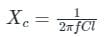
Effect of capacitance on performance of the short transmission lines is extremely small due to ________
Short Transmission Line:
When the length of the overhead transmission line is up to about 50 km and the line voltage is comparatively up to 20 kV.
Due to smaller lengths and lower voltage, the capacitance effect is small and maybe neglected, and hence Shunt admittance too.
Considered a short transmission line of resistance R and Reactance XL over a length.
Vs is the sending end voltage
VR is the receiving end voltage
I is the load current.
cos ϕR is receiving end power factor
and, cos ϕs is sending end power factor
The phasor diagram of the system can be drawn by taking load current as a reference,
From the phasor,
(OC)2 = (OD)2 + (DC)2
(OC)2 = (OE + ED)2 + (DB + BC)2
V2S = (VR cos ϕR + IR)2 + (VR sin ϕR + IXL)2
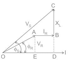
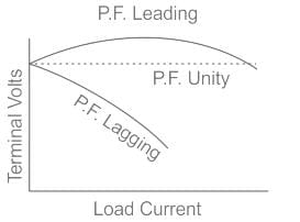
If the power factor is _____________, the voltage at the sending end is less than that at the receiving end in short line. Hence voltage regulation is negative.
Voltage regulation: The voltage regulation of transmission line is,
Percentage voltage regulation
Here,
Vs is the sending end voltage
Vr is the receiving end voltage
Voltage Regulation Curve at different Power Factor:
From The curve:
42 docs|34 tests
|
Use Code STAYHOME200 and get INR 200 additional OFF
|
Use Coupon Code |
42 docs|34 tests
|
|
|
|
|
|