Test: Signal Flow Graphs - 2 - Electrical Engineering (EE)


Test Description

10 Questions MCQ Test GATE Electrical Engineering (EE) 2024 Mock Test Series - Test: Signal Flow Graphs - 2

Test: Signal Flow Graphs - 2 for Electrical Engineering (EE) 2023 is part of GATE Electrical Engineering (EE) 2024 Mock Test Series preparation. The Test: Signal Flow Graphs - 2 questions and answers have been prepared according to the Electrical Engineering (EE) exam syllabus.The Test: Signal Flow Graphs - 2 MCQs are made for Electrical Engineering (EE) 2023 Exam. Find important definitions, questions, notes, meanings, examples, exercises, MCQs and online tests for Test: Signal Flow Graphs - 2 below.
Solutions of Test: Signal Flow Graphs - 2 questions in English are available as part of our GATE Electrical Engineering (EE) 2024 Mock Test Series for Electrical Engineering (EE) & Test: Signal Flow Graphs - 2 solutions in Hindi for GATE Electrical Engineering (EE) 2024 Mock Test Series course. Download more important topics, notes, lectures and mock test series for Electrical Engineering (EE) Exam by signing up for free. Attempt Test: Signal Flow Graphs - 2 | 10 questions in 30 minutes | Mock test for Electrical Engineering (EE) preparation | Free important questions MCQ to study GATE Electrical Engineering (EE) 2024 Mock Test Series for Electrical Engineering (EE) Exam | Download free PDF with solutions
1 Crore+ students have signed up on EduRev. Have you? Download the App
Test: Signal Flow Graphs - 2 - Question 1

Mason's rule is applied to

Detailed Solution for Test: Signal Flow Graphs - 2 - Question 1

Mason's rule or Mason’s gain formula is applied to signal flow graph for finding the transfer function.

Test: Signal Flow Graphs - 2 - Question 2

Assertion (A): Signal flow graph is applicable to the linear systems.
Reason (R): Signal flow graph method of finding the transfer function of a system is very simple and does not require any reduction technique.

Detailed Solution for Test: Signal Flow Graphs - 2 - Question 2

Signal flow graph is applicable to the linear systems because output is proportional to gain of the system

Reason (R) is also true but is not a correct explanation of assertion (A)

Test: Signal Flow Graphs - 2 - Question 3

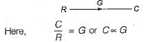
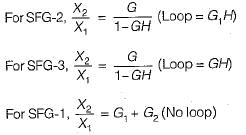
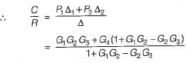
Consider the following three cases of signal flow graph and their corresponding transfer functions:

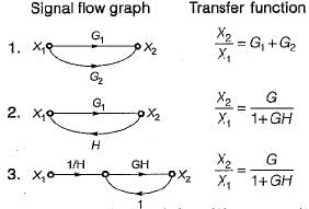
Q. Which of the above relations is/are correctly matched?

Detailed Solution for Test: Signal Flow Graphs - 2 - Question 3


Hence, only 1 is correctly matched.

Test: Signal Flow Graphs - 2 - Question 4

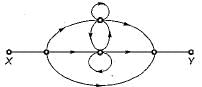
The signal flow graph shown below has M number of forward path and N number of individual loops.
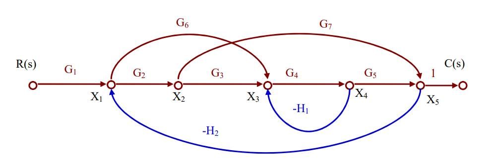
Q. ​What are the values of M and N ?

Detailed Solution for Test: Signal Flow Graphs - 2 - Question 4

There are three forward paths. The gain of the forward path are:

  • M1 = G1G2G3G4G5
  • M2 = G1G6G4G5
  • M3 = G1G2G7

There are four loops with loop gains:
N1= - G4H1

N2= - G2G7H2

N3= - G6G4G5H2

N4= - G2G3G4G5H2

Test: Signal Flow Graphs - 2 - Question 5

The signal flow graph for a certain feedback control system is given below.

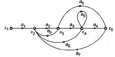
Now, consider the following set of equations for the nodes:

  1.  x2= a1x1+a5x3+a6x4+a7x5
  2. x3=a2x
  3. x4=a3x
  4. x5=a4x4+a8x3

Q. Which of the above equations are correct?

Detailed Solution for Test: Signal Flow Graphs - 2 - Question 5

Correct Answer :- b

Explanation : x2 = a1x1 + a5x3 + a6x4 + a7x5

x3 = a2x2

x4  a3x3 + a9x5

x5 = a4x4 + a8x3

Test: Signal Flow Graphs - 2 - Question 6

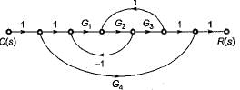
The gain C(s)/R(s) of the signal flow graph shown below is

Detailed Solution for Test: Signal Flow Graphs - 2 - Question 6

Gain of forward paths are:
P1 = G1G2G3 and P2 = G4
Here, Δ1 = 1
and Δ2 = (1 + G1G2— G2G3)
Individual loops are:
L1 = -G1G2
and L2 = G2G3
Non-touching loop = Nil

Test: Signal Flow Graphs - 2 - Question 7

The number of forward paths and the number of non-touching loop pairs for the signal flow graph shown in the figure below are respectively

Detailed Solution for Test: Signal Flow Graphs - 2 - Question 7

Forward paths are
P1 = G1G2G3 and P2 = G3G4
Gain product of non-touching loop pairs are:
L1 L2 = G1H1H4
and L1L3 = G1G3H1H2
Thus, there are two forward paths and two non touching loop pairs

Test: Signal Flow Graphs - 2 - Question 8

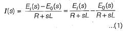
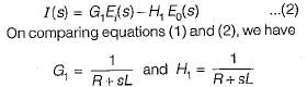
The signal flow graph of the RLC circuit of figure (i) is shown in figure (ii)

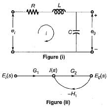
The values of G1 and H1 are respectively 

Detailed Solution for Test: Signal Flow Graphs - 2 - Question 8

Converting the given circuit in s-domain and writing the equations, we get:

Also, from given SFG, we have

Test: Signal Flow Graphs - 2 - Question 9

The closed loop transfer function CIR for the signal graph shown below is

Detailed Solution for Test: Signal Flow Graphs - 2 - Question 9

Number of forward paths are two, 

Test: Signal Flow Graphs - 2 - Question 10

Consider the following statements with regards to the signal flow graph shown below.

1. The number of forward paths are 2.
2. The number of forward paths are  5.
3. The number of loops are 3.
4. The number of loops are 5,
5. The number of non-touching loop pairs is 1.
6. The number of non-touching loop pairs is nil.

Q. Which of these statements are correct?

23 docs|285 tests
Information about Test: Signal Flow Graphs - 2 Page
In this test you can find the Exam questions for Test: Signal Flow Graphs - 2 solved & explained in the simplest way possible. Besides giving Questions and answers for Test: Signal Flow Graphs - 2, EduRev gives you an ample number of Online tests for practice
Download as PDF
Download free EduRev App
Track your progress, build streaks, highlight & save important lessons and more!