Test: Structural Analysis- 1 - Civil Engineering (CE) MCQ
10 Questions MCQ Test GATE Civil Engineering (CE) 2025 Mock Test Series - Test: Structural Analysis- 1

Match List - I (Method) with List-II (Factors) and select the correct answer using the codes given below the lists:
List - I
A. Moment distribution
B. Slope deflection
C. Kani’s method
D. Force method
List - II
1. Rotation factor
2. Flexibility
3. Hardy Cross
4. Displacements
5. Stiffness matrix
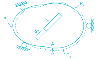
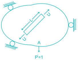
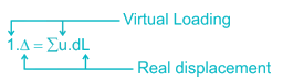
In the virtual work method of plastic analysis of steel structure, the virtual quantity is
| 1 Crore+ students have signed up on EduRev. Have you? Download the App |
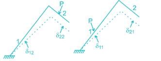
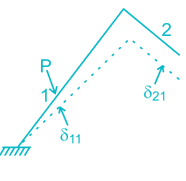
The figure below shows the displacement caused by load P at two points 1 and 2 respectively. According to Maxwell reciprocal theorem which option is CORRECT.

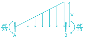
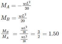
A fixed beam AB is subjected to a triangular load varying from zero at end A to ‘w’ per unit length at end B. The ratio of fixed end moment at B to A will be
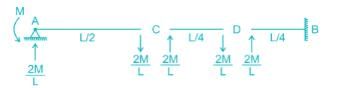
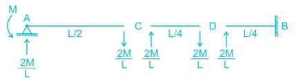
Find the carry over moment at support B, in the beam shown with internal hinges at C & D:-

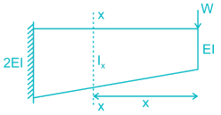
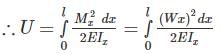
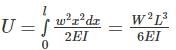
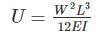
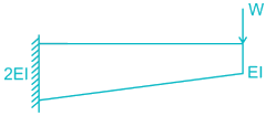
The strain energy stored (U) in the cantilever beam shown is –


 but greater than
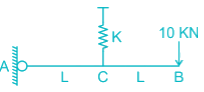
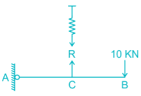
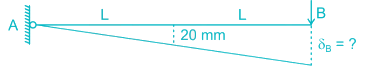
Find the vertical displacement of joint B if the spring constant k = 1 KN/mm and the rigid beam is loaded as shown below:-

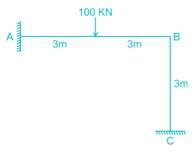
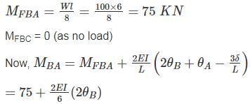
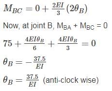
Find the rotation of joint B if the frame is loaded as shown below:
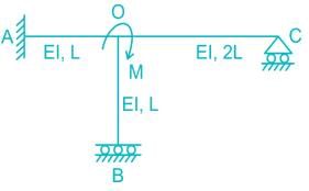
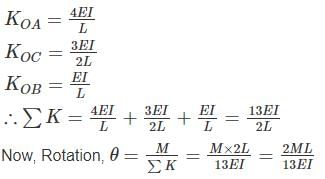
All members of the frame shown below have equal flexural rigidity EI. Calculate the rotation of joint O if moment M is applied?
|
31 docs|280 tests
|
|
31 docs|280 tests
|
Top Courses for Civil Engineering (CE)


Important Questions for Structural Analysis- 1
Structural Analysis- 1 MCQs with Answers
Online Tests for Structural Analysis- 1 GATE Civil Engineering (CE) 2025 Mock Test Series
|
© EduRev
|
Education Revolution
|


|


